Toyota Venza: Brake Pedal Load Sensing Switch
On-vehicle Inspection
ON-VEHICLE INSPECTION
PROCEDURE
1. INSPECT BRAKE PEDAL LOAD SENSING SWITCH
NOTICE:
- Do not remove the brake pedal load sensing switch from the brake pedal support assembly.
- When there is a malfunction in the brake pedal load sensing switch, replace the brake pedal support assembly.
(a) Disconnect the brake pedal load sensing switch connector.
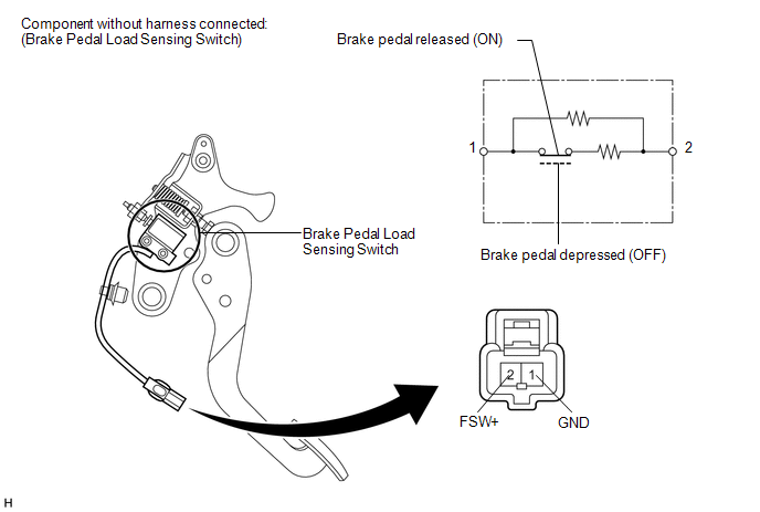
(b) Measure the resistance according to the value(s) in the table below.
Standard Resistance:
|
Tester Connection |
Condition |
Specified Condition |
|---|---|---|
|
2 (FSW+) - 1 (GND) |
Brake pedal load sensing switch OFF (Brake pedal depressed) |
950 to 1050 Ω |
|
2 (FSW+) - 1 (GND) |
Brake pedal load sensing switch ON (Brake pedal released) |
203 to 223 Ω |
If the value is not as specified, replace the brake pedal support assembly (See
page .gif) ).
).
 Installation
INSTALLATION
PROCEDURE
1. INSTALL BRAKE ACTUATOR ASSEMBLY
(a) Install the brake actuator assembly to the brake actuator bracket
assembly with the 2 nuts.
Torque:
8.0 N·m {82 ...

Other materials about Toyota Venza:
Power Source Mode does not Change to ON (ACC)
DESCRIPTION
When the engine switch is pushed with the electrical key in the cabin, the power
management control ECU receives signals to change the power source mode.
HINT:
To allow use of the Techstream to inspect the push-button start function when
the ...
A/C ECU Vehicle Information Reading/Writing Processor Malfunction (B15F5)
DESCRIPTION
This DTC is stored when items controlled by the air conditioning amplifier assembly
cannot be customized via the navigation system vehicle customization screen.
HINT:
The air conditioning amplifier assembly controls the air conditioning system ...
On-vehicle Inspection
ON-VEHICLE INSPECTION
PROCEDURE
1. INSPECT CAMSHAFT TIMING OIL CONTROL VALVE ASSEMBLY
(a) Connect the Techstream to the DLC3.
(b) Start the engine and turn the Techstream on.
(c) Inspect the oil control valve (for intake camshaft).
(1) Enter the followin ...

0.1301