Toyota Venza: Tire section names
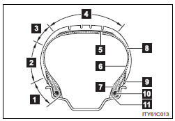
1. Bead
2. Sidewall
3. Shoulder
4. Tread
5. Belt
6. Inner liner
7. Reinforcing rubber
8. Carcass
9. Rim lines
10. Bead wires
11. Chafer
 Tire size
- Typical tire size information
The illustration indicates typical tire size.
1. Tire use
(P = Passenger car, T = Temporary use)
2. Section width (millimeters)
3. Aspect ratio
(tire heig ...
 Uniform Tire Quality Grading
This information has been prepared in accordance with regulations issued by the
National Highway Traffic Safety Administration of the U.S. Department of Transportation.
It provides the purchasers a ...
Other materials about Toyota Venza:
Installation
INSTALLATION
PROCEDURE
1. INSTALL FUEL INJECTOR ASSEMBLY
HINT:
Perform "Inspection After Repair" after replacing the fuel injector assembly
(See page ).
(a) Apply a light coat of gasoline or spindle oil to new O-rings, and
then ...
Installation
INSTALLATION
PROCEDURE
1. INSTALL NO. 3 ANTENNA CORD SUB-ASSEMBLY
(a) Pass the washer hose through the No. 3 antenna cord sub-assembly.
(b) Pass the No. 3 antenna cord sub-assembly with washer hose through
the vehicle body as shown in the il ...
Adjustment
ADJUSTMENT
PROCEDURE
1. PRECAUTIONS AND WORK DESCRIPTION
(a) The U660E automatic transaxle does not have an oil filler tube and oil level
gauge. When adding fluid, add fluid through the refill hole on the transaxle case.
The fluid level can be adjusted ...

0.1689