Toyota Venza: Throttle Actuator Control Throttle Body Range / Performance (P2119)
DESCRIPTION
The electronic throttle control system is composed of the throttle actuator, throttle position sensor, accelerator pedal position sensor, and ECM. The ECM operates the throttle actuator to regulate the throttle valve in response to driver inputs. The throttle position sensor detects the opening angle of the throttle valve, and provides the ECM with feedback so that the throttle valve can be appropriately controlled by the ECM.
|
DTC No. |
DTC Detection Condition |
Trouble Area |
|---|---|---|
|
P2119 |
The throttle valve opening angle continues to vary greatly from the target opening angle (1 trip detection logic). |
|
MONITOR DESCRIPTION
The ECM determines the actual opening angle of the throttle valve from the throttle position sensor signal. The actual opening angle is compared to the target opening angle commanded by the ECM. If the difference between these two values is outside the standard range, the ECM interprets this as a malfunction in the electronic throttle control system. The ECM then illuminates the MIL and stores the DTC.
MONITOR STRATEGY
|
Related DTCs |
P2119: Electronic Throttle Control System Malfunction |
|
Required Sensors/Components (Main) |
Throttle actuator (throttle body) |
|
Required Sensors/Components (Related) |
- |
|
Frequency of Operation |
Continuous |
|
Duration |
Closed: 1 second Open: 0.6 seconds |
|
MIL Operation |
Immediate |
|
Sequence of Operation |
None |
TYPICAL ENABLING CONDITIONS
|
Monitor runs whenever following DTCs not stored |
None |
|
System guard* judge condition |
ON |
|
*: System guard is ON when the following conditions are met: |
- |
|
Throttle actuator |
ON |
|
Throttle actuator duty calculation |
Executing |
|
Throttle position sensor fail |
Not detected |
|
Throttle actuator current-cut operation |
Not executing |
|
Throttle actuator power supply |
4 V or higher |
|
Throttle actuator fail |
Not detected |
TYPICAL MALFUNCTION THRESHOLDS
|
Either of following conditions A or B is met |
- |
|
A. Difference between commanded closed throttle position and current closed throttle position |
0.3 V or higher |
|
B. Difference between commanded open throttle position and current open throttle position |
0.3 V or higher |
CONFIRMATION DRIVING PATTERN
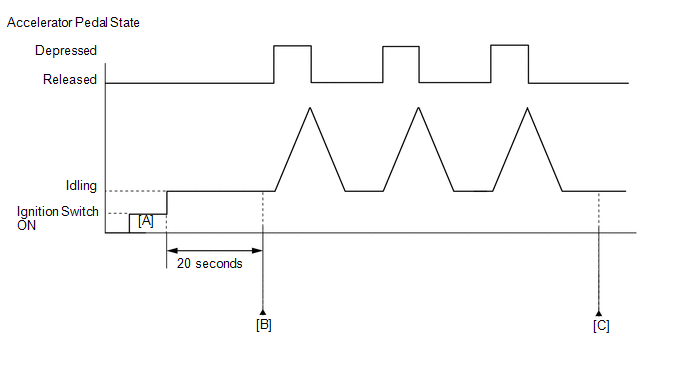
- Connect the Techstream to the DLC3.
- Turn the ignition switch to ON and turn the Techstream on.
- Clear the DTCs (even if no DTCs are stored, perform the clear DTC operation)
(See page
.gif) ).
). - Turn the ignition switch off and wait for at least 30 seconds.
- Turn the ignition switch to ON and turn the Techstream on [A].
- Start the engine.
- Idle the engine for 20 seconds.
- Enter the following menus: Powertrain / Engine / Trouble Codes [B].
- Read the Pending DTCs.
HINT:
- If a pending DTC is output, the system is malfunctioning.
- If a pending DTC is not output, perform the following procedure.
- Enter the following menus: Powertrain / Engine / Utility / All Readiness.
- Input the DTC: P2119.
- Check the DTC judgment result.
Techstream Display
Description
NORMAL
- DTC judgment completed
- System normal
ABNORMAL
- DTC judgment completed
- System abnormal
INCOMPLETE
- DTC judgment not completed
- Perform driving pattern after confirming DTC enabling conditions
N/A
- Unable to perform DTC judgment
- Number of DTCs which do not fulfill DTC preconditions has reached ECU memory limit
HINT:
- If the judgment result shows NORMAL, the system is normal.
- If the judgment result shows ABNORMAL, the system has a malfunction.
- If the judgment result shows INCOMPLETE or N/A, fully depress and release the accelerator pedal 3 times, and then check the DTC judgment result at step [C].
- If no pending DTC is output, perform a universal trip and check for
permanent DTCs (See page ).
HINT:
- If a permanent DTC is output, the system is malfunctioning.
- If no permanent DTC is output, the system is normal.
FAIL-SAFE
When this DTC, as well as other DTCs relating to Electronic Throttle Control System (ETCS) malfunctions, is stored, the ECM enters fail-safe mode. During fail-safe mode, the ECM cuts the current to the throttle actuator, and the throttle valve is returned to a 6° throttle angle by the return spring. The ECM then adjusts the engine output by controlling the fuel injection (intermittent fuel-cut) and ignition timing, in accordance with the accelerator pedal opening angle, to allow the vehicle to continue running at a minimal speed. If the accelerator pedal is depressed firmly and gently, the vehicle can be driven slowly.
Fail-safe mode continues until a pass condition is detected, and the ignition switch is then turned off.
WIRING DIAGRAM
Refer to DTC P2102 (See page ).
CAUTION / NOTICE / HINT
HINT:
- Refer to "Data List / Active Test" [Throttle Position Command, Throttle
Position No. 1, Throttle Motor Current, Throttle Motor Duty (Open), Throttle
Motor Duty (Close)] (See page ).
- Read freeze frame data using the Techstream. The ECM records vehicle and driving condition information as freeze frame data the moment a DTC is stored. When troubleshooting, freeze frame data can help determine if the vehicle was moving or stationary, if the engine was warmed up or not, if the air fuel ratio was lean or rich, and other data from the time the malfunction occurred.
PROCEDURE
|
1. |
CHECK ANY OTHER DTCS OUTPUT (IN ADDITION TO DTC P2119) |
(a) Connect the Techstream to the DLC3.
(b) Turn the ignition switch to ON.
(c) Turn the Techstream on.
(d) Enter the following menus: Powertrain / Engine / Trouble Codes.
(e) Read the DTCs.
|
Result |
Proceed to |
|---|---|
|
DTC P2119 is output |
A |
|
DTC P2119 and other DTCs are output |
B |
HINT:
If any DTCs other than P2119 are output, troubleshoot those DTCs first.
| B | .gif) |
GO TO DTC CHART |
|
.gif)
|
2. |
READ VALUE USING TECHSTREAM (THROTTLE POSITION) |
(a) Connect the Techstream to the DLC3.
(b) Turn the ignition switch to ON.
(c) Turn the Techstream on.
(d) Clear the DTCs (See page ).
(e) Turn the ignition switch off and wait for at least 30 seconds.
(f) Turn the ignition switch to ON.
(g) Enter the following menus: Powertrain / Engine / Data List / Throttle Position No. 1 and Throttle Position Command.
(h) Check the values displayed on the Techstream while fully depressing and releasing the accelerator pedal quickly.
Result|
Result |
Proceed to |
|---|---|
|
Throttle Position No. 1 does not change |
A |
|
Throttle Position No. 1 changes even a little |
B |
HINT:
When a DTC is output, the system changes to fail-safe mode. Therefore, only use the data up until the time the DTC is stored for confirmation.
| B | |
GO TO STEP 4 |
|
|
3. |
INSPECT THROTTLE BODY ASSEMBLY (RESISTANCE OF THROTTLE ACTUATOR) |
(a) Inspect the throttle body assembly (See page
).
| NG | |
GO TO STEP 7 |
|
|
4. |
INSPECT THROTTLE BODY ASSEMBLY (VISUALLY CHECK THROTTLE VALVE) |
(a) Check for contamination between the throttle valve and housing. If necessary, clean the throttle body. Also, check that the throttle valve moves smoothly.
OK:
Throttle valve is not contaminated with foreign objects and moves smoothly.
| NG | |
GO TO STEP 7 |
|
|
5. |
READ VALUE USING TECHSTREAM (THROTTLE POSITION) |
(a) Connect the Techstream to the DLC3.
(b) Turn the ignition switch to ON.
(c) Turn the Techstream on.
(d) Clear the DTCs (See page ).
(e) Turn the ignition switch off and wait for at least 30 seconds.
(f) Turn the ignition switch to ON.
(g) Enter the following menus: Powertrain / Engine / Data List / Throttle Position No. 1, Throttle Position No. 2 and Throttle Position Command.
(h) Check the values displayed on the Techstream while wiggling the ECM wire harness.
(i) Enter the following menus: Powertrain / Engine / Trouble Codes.
(j) Check for DTCs.
Result|
Result |
Proceed to |
|---|---|
|
Value in Data List changes when wire harness is wiggled, or DTC is output |
A |
|
Other than above |
B |
| B | |
GO TO STEP 8 |
|
|
6. |
REPAIR OR REPLACE HARNESS OR CONNECTOR (ECM - THROTTLE BODY) |
(a) As the DTC was stored due to a change in the contact resistance of the connector,
repair or replace the wire harness or connector (See page
).
| NEXT | |
END |
|
7. |
REPLACE THROTTLE BODY ASSEMBLY |
(a) Replace the throttle body assembly (See page
).
HINT:
Perform "Inspection After Repair" after replacing the throttle body (See page
).
|
|
8. |
CHECK WHETHER DTC OUTPUT RECURS (DTC P2119) |
(a) Connect the Techstream to the DLC3.
(b) Turn the ignition switch to ON.
(c) Turn the Techstream on.
(d) Clear the DTCs (See page ).
(e) Turn the ignition switch off and wait for at least 30 seconds.
(f) Allow the engine to idle for 15 seconds or more.
(g) Fully depress and release the accelerator pedal several times quickly.
(h) Enter the following menus: Powertrain / Engine / Trouble Codes.
(i) Read the DTCs.
|
Result |
Proceed to |
|---|---|
|
DTC is not output |
A |
|
DTC P2119 is output |
B |
| A | |
END |
| B | |
REPLACE ECM |
 Throttle Actuator Control Motor Current Range / Performance (P2118)
DESCRIPTION
The electronic throttle control system has a dedicated power supply circuit.
The voltage (+BM) is monitored and when it is low (below 4 V), the ECM determines
that there is a malfunct ...
 Throttle / Pedal Position Sensor / Switch "D" Circuit (P2120,P2122,P2123,P2125,P2127,P2128,P2138)
DESCRIPTION
HINT:
This Electronic Throttle Control System (ETCS) does not use a throttle
cable.
These DTCs relate to the accelerator pedal sensor assembly.
The accelerator ped ...
Other materials about Toyota Venza:
Removal
REMOVAL
CAUTION / NOTICE / HINT
HINT:
The front side fix window assembly can be reused. When installing the
window, if any of the clips on the quarter window glass are broken, butyl
tape can be used to support the glass until the applied adh ...
Dtc Check / Clear
DTC CHECK / CLEAR
1. CHECK DTC (CHECK USING TECHSTREAM)
(a) Connect the Techstream to the DLC3.
(b) Turn the ignition switch to ON.
(c) Turn the Techstream on.
(d) Enter the following menus: Body Electrical / Navigation System / Trouble
Codes.
(e) Chec ...
Checking and replacing fuses
If any of the electrical components do not operate, a fuse may have blown.
If this happens, check and replace the fuses as necessary.
Vehicles with smart key system:
Turn the “ENGINE START STOP” switch off.
Vehicles without smart key system:
Turn th ...

0.1376