Toyota Venza: Test Mode Procedure
TEST MODE PROCEDURE
1. WARNING LIGHT AND INDICATOR LIGHT INITIAL CHECK
(a) Release the parking brake.
NOTICE:
Before releasing the parking brake, move the shift lever to P for safety.
HINT:
When the parking brake is applied or the brake fluid level is low, the brake warning light comes on.
(b) When the ignition switch is turned to ON, check that the ABS warning, brake warning, TRAC OFF indicator, VSC OFF indicator and slip indicator lights all come on for approximately 3 seconds.
HINT:
- If the skid control ECU stores any DTCs, the ABS warning and slip indicator lights will come on.
- If any of the indicators remains on or does not come on, proceed to troubleshooting for the light circuits listed below.
|
Trouble Area |
See Procedure |
|---|---|
|
ABS warning light circuit (Remains on) |
|
|
ABS warning light circuit (Does not come on) |
|
|
Brake warning light circuit (Remains on) |
|
|
Brake warning light circuit (Does not come on) |
|
|
TRAC OFF indicator light circuit (Remains on) |
|
|
TRAC OFF indicator light circuit (Does not come on) |
|
|
VSC OFF indicator light circuit (Remains on) |
|
|
VSC OFF indicator light circuit (Does not come on) |
|
|
Slip indicator light circuit (Remains on) |
|
|
Slip indicator light circuit (Does not come on) |
|
.gif)
2. SENSOR CHECK USING TEST MODE (SIGNAL CHECK) (When Using the Techstream)
HINT:
DTCs are stored if any malfunctions are detected during each sensor check.
(a) Procedure to enter Test Mode
(1) Turn the ignition switch off.
(2) Check that the steering wheel is centered.
(3) Check that the shift lever is in P.
(4) Connect the Techstream to the DLC3.
(5) Turn the ignition switch to ON.
(6) Turn the Techstream on.
(7) Switch the skid control ECU to Test Mode using the Techstream. Enter the following menus: Chassis / ABS/VSC/TRAC / Utility / Signal Check.
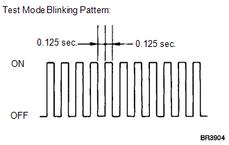
(8) Check that the ABS warning and slip indicator lights come on for several seconds and then blink in Test Mode.
.png)
HINT:
- The TRAC OFF indicator light remains on during Test Mode because TRAC is prohibited.
- If the ABS warning and slip indicator lights do not blink, inspect the TS and CG terminal circuit and ABS warning and slip indicator light circuits.
(9) Check the ABS sensors.
HINT:
Check that the ABS warning light is blinking in the Test Mode blinking pattern before performing the ABS sensor check.
(b) Lost Booster Pressure Judgement Check
NOTICE:
Perform the check in the lost booster pressure state (negative pressure in the booster is depressurized).
(1) Turn the ignition switch to ON.
(2) Check that the brake warning light comes on when depressing the brake pedal with a force of 65.5 N (6.7 kgf, 15.0 lbf) or more for 1 second or more. (The lost booster pressure state is judged to be normal.)
(3) Start the engine while depressing the brake pedal with a force of 65.5 N (6.7 kgf, 15.0 lbf) or more for 1 second or more.
(4) Check that the brake warning light goes off when quickly releasing the brake pedal. (The lost booster pressure state is judged to be normal.)
NOTICE:
- If the lost booster pressure judgment check is not completed normally, the master cylinder pressure sensor check is not judged.
- If a recheck is performed after the engine has started, end the Test Mode, enter Test Mode again, and release the vacuum in the booster by pumping the brake pedal prior to the recheck.
HINT:
If the lost booster pressure state is not judged to be normal, the brake warning light comes on and Test Mode DTC C1281 (Master Cylinder Pressure Sensor Output Malfunction) is recorded.
(c) Speed Sensor Check
(1) Drive the vehicle straight-ahead.
Accelerate the vehicle to a speed of 45 km/h (28 mph) or more for several seconds.
(2) Check that the ABS warning light goes off.
HINT:
- The sensor check may not be completed if wheel spin occurs.
- The ABS warning light goes off when the sensor check has been completed.
- The ABS warning light comes on immediately after a malfunction has been detected during the speed sensor check.
(3) Stop the vehicle.
NOTICE:
- The speed sensor check may not be completed if the speed sensor check is started while turning the steering wheel or spinning the wheels.
- If the sensor check has not been completed, the ABS warning light will blink while driving and the ABS system will not operate.
- After the ABS warning light goes off, if the vehicle speed exceeds 80
km/h (50 mph), a sensor check code will be stored again.
Decelerate or stop the vehicle before the speed reaches 80 km/h (50 mph).
HINT:
When the sensor check has been completed, the ABS warning light goes off while driving and blinks in the Test Mode pattern while stationary.
(d) VSC OFF Switch Check
(1) Check that the TRAC OFF indicator light comes on and VSC OFF indicator light goes off.
(2) Press the VSC OFF switch.
(3) Check that the TRAC OFF indicator light goes off.
(4) Press and hold the VSC OFF switch for 3 seconds or more.
(5) Check that the TRAC OFF indicator and VSC OFF indicator lights come on.
(e) End of Sensor Check
(1) If the sensor check is completed, the ABS warning light blinks (Test Mode) when the vehicle stops and the ABS warning light is off while the vehicle is driving.
NOTICE:
If the sensor check has not been completed, the ABS warning light will blink while driving and the ABS system will not operate.
(f) Read Sensor Check DTCs
(1) Read the DTC(s) by following the Techstream screen.
NOTICE:
- If only DTCs other than Test Mode sensor check DTCs are displayed, repair the malfunctions and clear the DTCs.
- If Test Mode sensor check DTCs and other DTCs are displayed or if only Test Mode sensor check DTCs are displayed, repair the malfunctions, clear the DTCs, and perform Test Mode inspection again.
HINT:
See "Sensor Check DTCs".
(2) Turn the ignition switch off and disconnect the Techstream.
(g) Sensor Check DTCs
ABS Sensor|
DTC Code |
Detection Item |
Trouble Area |
|---|---|---|
|
C1271 |
Low Output Signal of Front Speed Sensor RH |
|
|
C1272 |
Low Output Signal of Front Speed Sensor LH |
|
|
C1273 |
Low Output Signal of Rear Speed Sensor RH |
|
|
C1274 |
Low Output Signal of Rear Speed Sensor LH |
|
|
C1275 |
Abnormal Change in Output Signal of Front Speed Sensor RH |
Speed sensor rotor |
|
C1276 |
Abnormal Change in Output Signal of Front Speed Sensor LH |
Speed sensor rotor |
|
C1277 |
Abnormal Change in Output Signal of Rear Speed Sensor RH |
Speed sensor rotor |
|
C1278 |
Abnormal Change in Output Signal of Rear Speed Sensor LH |
Speed sensor rotor |
|
C1281 |
Master Cylinder Pressure Sensor Output Malfunction |
|
HINT:
The codes in this table are output only in Test Mode (signal check).
3. SENSOR CHECK USING TEST MODE (SIGNAL CHECK) (When not Using the Techstream)
HINT:
DTCs are stored if any malfunctions are detected during each sensor check.
(a) Procedure to enter Test Mode
(1) Turn the ignition switch off.
(2) Check that the steering wheel is centered.
(3) Check that the shift lever is in P.
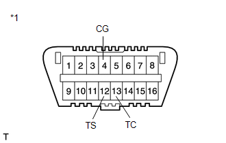
(4) Using SST, connect terminals TS and CG of the DLC3.
.png)
SST: 09843-18040
Text in Illustration|
*1 |
Front view of DLC3 |
(5) Turn the ignition switch to ON.
(6) Check that the ABS warning and slip indicator lights come on for several seconds and then blink in Test Mode.
HINT:
- The TRAC OFF indicator light remains on during Test Mode because TRAC is prohibited.
- If the ABS warning and slip indicator lights do not blink, inspect the TS and CG terminal circuit and ABS warning and slip indicator light circuits.
(7) Check the ABS sensors.
HINT:
Check that the ABS warning light is blinking in the Test Mode blinking pattern before performing the ABS sensor check.
(b) Lost Booster Pressure Judgement Check
NOTICE:
Perform the check in the lost booster pressure state (negative pressure in the booster is depressurized).
(1) Turn the ignition switch to ON.
(2) Check that the brake warning light comes on when depressing the brake pedal with a force of 65.5 N (6.7 kgf, 15.0 lbf) or more for 1 second or more. (The lost booster pressure state is judged to be normal.)
(3) Start the engine while depressing the brake pedal with a force of 65.5 N (6.7 kgf, 15.0 lbf) or more for 1 second or more.
(4) Check that the brake warning light goes off when quickly releasing the brake pedal. (The lost booster pressure state is judged to be normal.)
NOTICE:
- If the lost booster pressure judgment check is not completed normally, the master cylinder pressure sensor check is not judged.
- If a recheck is performed after the engine has started, end the Test Mode, enter Test Mode again, and release the vacuum in the booster by pumping the brake pedal prior to the recheck.
HINT:
If the lost booster pressure state is not judged to be normal, the brake warning light comes on and Test Mode DTC 81 (Master Cylinder Pressure Sensor Output Malfunction) is recorded.
(c) Speed Sensor Check
(1) Drive the vehicle straight-ahead.
Accelerate the vehicle to a speed of 45 km/h (28 mph) or more for several seconds.
(2) Check that the ABS warning light goes off.
HINT:
- The sensor check may not be completed if wheel spin occurs.
- The ABS warning light goes off when the sensor check has been completed.
- The ABS warning light comes on immediately after a malfunction has been detected during the speed sensor check.
(3) Stop the vehicle.
NOTICE:
- The speed sensor check may not be completed if the speed sensor check is started while turning the steering wheel or spinning the wheels.
- If the sensor check has not been completed, the ABS warning light will blink while driving and the ABS system will not operate.
- After the ABS warning light goes off, if the vehicle speed exceeds 80
km/h (50 mph), a sensor check code will be stored again.
Decelerate or stop the vehicle before the speed reaches 80 km/h (50 mph).
HINT:
When the sensor check has been completed, the ABS warning light goes off while driving and blinks in the Test Mode pattern while stationary.
(d) VSC OFF Switch Check
(1) Check that the TRAC OFF indicator light comes on and VSC OFF indicator light goes off.
(2) Press the VSC OFF switch.
(3) Check that the TRAC OFF indicator light goes off.
(4) Press and hold the VSC OFF switch for 3 seconds or more.
(5) Check that the TRAC OFF indicator and VSC OFF indicator lights come on.
(e) End of Sensor Check
(1) If the sensor check is completed, the ABS warning light blinks (Test Mode) when the vehicle stops and the ABS warning light is off while the vehicle is driving.
NOTICE:
If the sensor check has not been completed, the ABS warning light will blink while driving and the ABS system will not operate.
(f) Read Sensor Check DTCs
(1) Using SST, connect terminals TC and CG of the DLC3.
SST: 09843-18040
Text in Illustration|
*1 |
Front view of DLC3 |
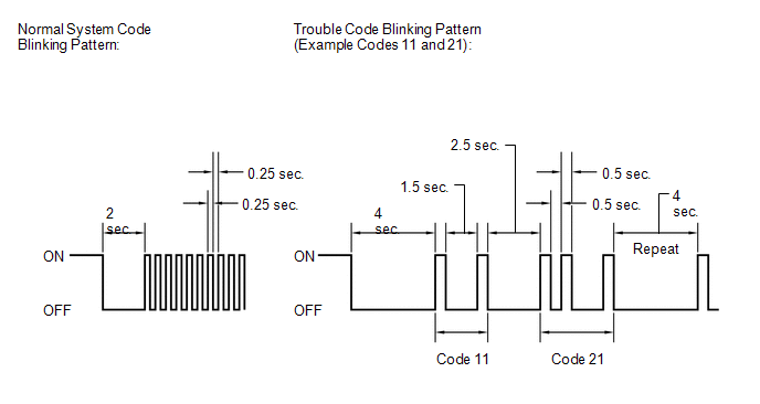
(2) Count the number of blinks of the ABS warning and slip indicator lights.
NOTICE:
- If only DTCs other than Test Mode sensor check DTCs are displayed, repair the malfunctions and clear the DTCs.
- If Test Mode sensor check DTCs and other DTCs are displayed or if only Test Mode sensor check DTCs are displayed, repair the malfunctions, clear the DTCs, and perform Test Mode inspection again.
HINT:
- If more than 1 malfunction is detected at the same time, the lowest numbered code will be displayed first.
- See "Sensor Check DTCs".
(3) After performing the check, disconnect SST from terminals TS and CG, and TC and CG of the DLC3, and turn the ignition switch off.
(4) Turn the ignition switch to ON to cancel the Test Mode.
HINT:
- If the ignition switch is not turned to ON after SST is removed from the DLC3, the previous Test Mode will continue.
- If the ignition switch is turned to ON with terminals TS and CG shorted, the previous Test Mode will continue.
(g) Sensor Check DTCs
ABS Sensor|
DTC Code |
Detection Item |
Trouble Area |
|---|---|---|
|
71 |
Low Output Signal of Front Speed Sensor RH |
|
|
72 |
Low Output Signal of Front Speed Sensor LH |
|
|
73 |
Low Output Signal of Rear Speed Sensor RH |
|
|
74 |
Low Output Signal of Rear Speed Sensor LH |
|
|
75 |
Abnormal Change in Output Signal of Front Speed Sensor RH |
Speed sensor rotor |
|
76 |
Abnormal Change in Output Signal of Front Speed Sensor LH |
Speed sensor rotor |
|
77 |
Abnormal Change in Output Signal of Rear Speed Sensor RH |
Speed sensor rotor |
|
78 |
Abnormal Change in Output Signal of Rear Speed Sensor LH |
Speed sensor rotor |
|
81 |
Master Cylinder Pressure Sensor Output Malfunction |
|
HINT:
The codes in this table are output only in Test Mode (signal check).
 Check For Intermittent Problems
CHECK FOR INTERMITTENT PROBLEMS
1. CHECK FOR INTERMITTENT PROBLEMS
HINT:
A momentary interruption (open circuit) in the connectors and/or wire harness
between the sensors and ECUs can be detected ...
 Problem Symptoms Table
PROBLEM SYMPTOMS TABLE
If there are no DTCs output and the problem still occurs, check the circuits
for each problem symptom in the order given in the following table and proceed to
the relevant ...
Other materials about Toyota Venza:
Data List / Active Test
DATA LIST / ACTIVE TEST
1. DATA LIST
HINT:
Using the Techstream to read the Data List allows the values or states of switches,
sensors, actuators and other items to be read without removing any parts. This non-intrusive
inspection can be very useful bec ...
Replacement
REPLACEMENT
PROCEDURE
1. REPLACE RING PIN
NOTICE:
It is not necessary to remove the ring pin unless it is being replaced.
(a) Remove the 12 ring pins.
(b) Using a plastic-faced hammer, install 12 new ring pins.
Standard Protrusion Height:
...
Precaution
PRECAUTION
1. PRECAUTION FOR DISCONNECTING CABLE FROM NEGATIVE BATTERY TERMINAL
NOTICE:
After the ignition switch is turned off, the navigation receiver assembly
records various types of memory and settings. As a result, after turning
the ig ...

0.1648