Toyota Venza: Replacement
REPLACEMENT
PROCEDURE
1. REPLACE RING PIN
NOTICE:
It is not necessary to remove the ring pin unless it is being replaced.
(a) Remove the 12 ring pins.
(b) Using a plastic-faced hammer, install 12 new ring pins.
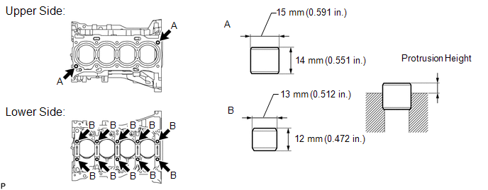
Standard Protrusion Height:
|
Item |
Specified Condition |
|---|---|
|
A |
5.0 to 7.0 mm (0.197 to 0.276 in.) |
|
B |
4.0 to 7.0 mm (0.157 to 0.276 in.) |
2. REPLACE STRAIGHT PIN
NOTICE:
It is not necessary to remove the straight pin unless it is being replaced.
(a) Remove the 14 straight pins.
(b) Using a plastic-faced hammer, install 14 new straight pins.
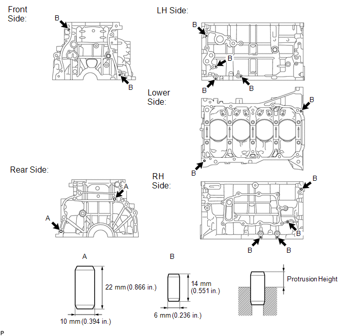
Standard Protrusion Height:
|
Item |
Specified Condition |
|---|---|
|
A |
11.0 to 13.0 mm (0.433 to 0.512 in.) |
|
B |
5.0 to 7.0 mm (0.197 to 0.276 in.) |
 Reassembly
REASSEMBLY
CAUTION / NOTICE / HINT
HINT:
Perform "Inspection After Repair" after replacing the piston or piston ring (See
page ).
PROCEDURE
1. INSTALL STUD BOLT
NOTICE:
If a stud b ...
 Cylinder Head
...
Other materials about Toyota Venza:
Automatic High Beam System (B124B)
DESCRIPTION
The DTC is stored when the main body ECU (driver side junction block assembly)
detects malfunctions in the automatic high beam system.
DTC No.
DTC Detection Condition
Trouble Area
B124B
...
Disposal
DISPOSAL
CAUTION / NOTICE / HINT
CAUTION:
Before performing pre-disposal deployment of any SRS component, review and closely
follow all applicable environmental and hazardous material regulations. Pre-disposal
deployment may be considered hazardous mate ...
Outer Mirror Control Ecu
Components
COMPONENTS
ILLUSTRATION
Removal
REMOVAL
PROCEDURE
1. REMOVE FRONT DOOR INSIDE HANDLE BEZEL PLUG
2. REMOVE POWER WINDOW REGULATOR MASTER SWITCH ASSEMBLY WITH FRONT DOOR ARMREST
BASE PANEL (for Driver Side)
3. REMOVE POWER WINDOW ...

0.1479