Toyota Venza: Terminals Of Ecu
TERMINALS OF ECU
1. CHECK COMBINATION METER ASSEMBLY
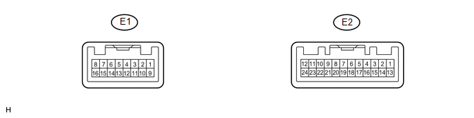
(a) Measure the resistance and voltage according to the value(s) in the table below.
|
Tester Connection |
Wiring Color |
Terminal Description |
Condition |
Specified Condition |
|---|---|---|---|---|
|
E2-14 (B) - Body ground |
Y - Body ground |
Battery power supply |
Always |
11 to 14 V |
|
E2-13 (IG+) - Body ground |
BR - Body ground |
Ignition switch power supply |
Ignition switch ON |
11 to 14 V |
|
E2-13 (IG+) - Body ground |
BR - Body ground |
Ignition switch power supply |
Ignition switch off |
Below 1 V |
|
E2-11 (E1) - Body ground |
B - Body ground |
Ground |
Always |
Below 1 Ω |
|
E2-24 (ES) - Body ground |
W - Body ground |
Ground |
Always |
Below 1 Ω |
|
E1-1 (CANH) - Body ground |
LG - Body ground |
CAN communication line |
Always |
200 Ω or higher |
|
E1-9 (CANL) - Body ground |
W - Body ground |
CAN communication line |
Always |
200 Ω or higher |
|
E1-5 (P/SB) - Body ground |
G - Body ground |
Front passenger side seat belt warning light signal |
Front passenger side seat occupied, seat belt fastened |
11 to 14 V |
|
E1-5 (P/SB) - Body ground |
G - Body ground |
Front passenger side seat belt warning light signal |
Front passenger side seat occupied, seat belt unfastened |
Below 1 V |
- If the result is not as specified, the combination meter assembly may have a malfunction.
2. CHECK ACCESSORY METER ASSEMBLY

(a) Measure the resistance and voltage according to the value(s) in the table below.
|
Tester Connection |
Wiring Color |
Terminal Description |
Condition |
Specified Condition |
|---|---|---|---|---|
|
F2-1 (B) - Body ground |
P - Body ground |
Battery power supply |
Always |
11 to 14 V |
|
F2-13 (IG+) - Body ground |
L - Body ground |
Ignition switch power supply |
Ignition switch ON |
11 to 14 V |
|
F2-13 (IG+) - Body ground |
L - Body ground |
Ignition switch power supply |
Ignition switch off |
Below 1 V |
|
F2-12 (E) - Body ground |
B - Body ground |
Ground |
Always |
Below 1 Ω |
|
F2-20 (PBEW) - Body ground |
G - Body ground |
Front passenger side seat belt warning light signal |
Front passenger side seat occupied, seat belt fastened |
11 to 14 V |
|
F2-20 (PBEW) - Body ground |
G - Body ground |
Front passenger side seat belt warning light signal |
Front passenger side seat occupied, seat belt unfastened |
Below 1 V |
- If the result is not as specified, the accessory meter assembly may have a malfunction.
3. CHECK CENTER AIRBAG SENSOR ASSEMBLY
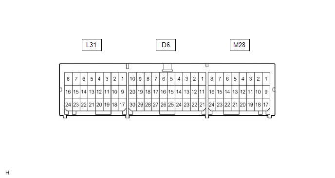
|
Terminal No. |
Terminal Symbol |
Destination |
|---|---|---|
|
M28-16 |
FSR+ |
Occupant classification ECU |
|
M28-24 |
FSR- |
Occupant classification ECU |
|
L31-10 |
LBE+ |
Front seat inner belt assembly (for driver side) |
|
L31-18 |
LBE- |
Front seat inner belt assembly (for driver side) |
4. CHECK OCCUPANT CLASSIFICATION ECU
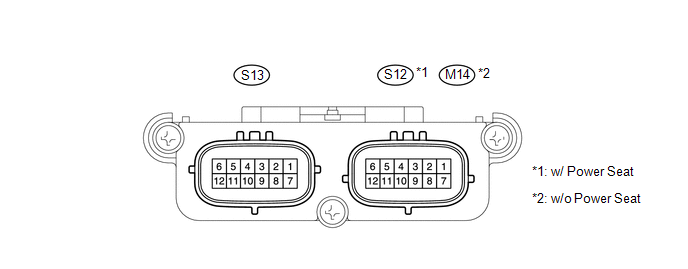
(a) Measure the voltage according to the value(s) in the table below.
|
Tester Connection |
Wiring Color |
Terminal Description |
Condition |
Specification |
|---|---|---|---|---|
|
S12-1 (+B) - S12-3 (GND)*1 M14-1 (+B) - M14-3 (GND)*2 |
GR - W-B*1 G - W-B*2 |
Battery power supply |
Always |
10 to 14 V |
|
S12-2 (DIA) - S12-3 (GND)*1 M14-2 (DIA) - M14-3 (GND)*2 |
SB - W-B |
Diagnosis (DLC3) |
Ignition switch ON |
Pulse generation |
|
S12-3 (GND) - Body ground*1 M14-3 (GND) - Body ground*2 |
W-B - Body ground |
Ground |
Always |
Below 1 V |
|
S12-7 (IG) - S12-3 (GND)*1 M14-7 (IG) - M14-3 (GND)*2 |
V - W-B |
Ignition switch power supply |
Ignition switch ON |
10 to 14 V |
|
S12-8 (FSR+) - S12-4 (FSR-)*1 M14-8 (FSR+) - M14-4 (FSR-)*2 |
W - B |
Center airbag sensor assembly communication line |
Ignition switch ON |
Pulse generation |
|
S12-9 (BSW) - S12-5 (BGND)*1 M14-9 (BSW) - M14-5 (BGND)*2 |
L - GR*1 G - Y*2 |
Front passenger side buckle switch line |
Always |
4 to 14 V |
|
S13-1 (SGD1) - S12-3 (GND)*1 S13-1 (SGD1) - M14-3 (GND)*2 |
R - W-B*1 Y - W-B*2 |
Front occupant classification sensor LH ground line |
Always |
Below 1 V |
|
S13-2 (SGD2) - S12-3 (GND)*1 S13-2 (SGD2) - M14-3 (GND)*2 |
Y - W-B*1 SB - W-B*2 |
Front occupant classification sensor RH ground line |
Always |
Below 1 V |
|
S13-3 (SGD3) - S12-3 (GND)*1 S13-3 (SGD3) - M14-3 (GND)*2 |
BR - W-B*1 L - W-B*2 |
Rear occupant classification sensor LH ground line |
Always |
Below 1 V |
|
S13-4 (SGD4) - S12-3 (GND)*1 S13-4 (SGD4) - M14-3 (GND)*2 |
LG - W-B*1 W - W-B*2 |
Rear occupant classification sensor RH ground line |
Always |
Below 1 V |
|
S13-11 (SVC1) - S13-1 (SGD1) |
Y - R*1 P - Y*2 |
Front occupant classification sensor LH power supply line |
Ignition switch ON, a load applied to front occupant classification sensor LH |
4.9 to 5.1 V |
|
S13-12 (SVC2) - S13-2 (SGD2) |
V - Y*1 BR - SB*2 |
Front occupant classification sensor RH power supply line |
Ignition switch ON, a load applied to front occupant classification sensor RH |
4.9 to 5.1 V |
|
S13-5 (SVC3) - S13-3 (SGD3) |
G - BR*1 R - L*2 |
Rear occupant classification sensor LH power supply line |
Ignition switch ON, a load applied to rear occupant classification sensor LH |
4.9 to 5.1 V |
|
S13-6 (SVC4) - S13-4 (SGD4) |
GR - LG*1 B - W*2 |
Rear occupant classification sensor RH power supply line |
Ignition switch ON, a load applied to rear occupant classification sensor RH |
4.9 to 5.1 V |
|
S13-7 (SIG1) - S13-1 (SGD1) |
P - R*1 BE - Y*2 |
Front occupant classification sensor LH signal line |
Ignition switch ON, a load applied to front occupant classification sensor LH |
0 to 5.1 V |
|
S13-8 (SIG2) - S13-2 (SGD2) |
GR - Y*1 GR - SB*2 |
Front occupant classification sensor RH signal line |
Ignition switch ON, a load applied to front occupant classification sensor RH |
0 to 5.1 V |
|
S13-9 (SIG3) - S13-3 (SGD3) |
L - BR*1 G - L*2 |
Rear occupant classification sensor LH signal line |
Ignition switch ON, a load applied to rear occupant classification sensor LH |
0 to 5.1 V |
|
S13-10 (SIG4) - S13-4 (SGD4) |
SB - LG*1 V - W*2 |
Rear occupant classification sensor RH signal line |
Ignition switch ON, a load applied to rear occupant classification sensor RH |
0 to 5.1 V |
- *1: w/ Power Seat
- *2: w/o Power Seat
- If the result is not as specified, the occupant detection ECU may have a malfunction.
 Diagnosis System
DIAGNOSIS SYSTEM
1. CHECK DLC3
(a) Check the DLC3 (See page ).
2. INSPECT BATTERY VOLTAGE
(a) Measure the battery voltage.
Standard Voltage:
11 to 14 V
If the voltage is below 11 V, recharge ...
 Data List / Active Test
DATA LIST / ACTIVE TEST
1. DATA LIST
HINT:
Using the Techstream to read the Data List allows the values or states of switches,
sensors, actuators and other items to be read without removing any p ...
Other materials about Toyota Venza:
Definition Of Terms
DEFINITION OF TERMS
Term
Definition
Monitor Description
Description of what the ECM monitors and how it detects malfunctions
(monitoring purpose and details).
Related DTCs
Group ...
Initialization
INITIALIZATION
1. INITIALIZE POWER WINDOW CONTROL SYSTEM (POWER WINDOW REGULATOR MOTOR ASSEMBLY
(ALL DOORS))
CAUTION:
When the power window regulator motor assembly is reinstalled or replaced, the
power window control system must be initialized. Functio ...
Differential Mount Cushion
Components
COMPONENTS
ILLUSTRATION
Installation
INSTALLATION
PROCEDURE
1. INSTALL REAR NO. 1 DIFFERENTIAL MOUNT CUSHION
(a) Using SST, install a new rear No. 1 differential mount cushion.
Text in Illustration
*1
Protrusion ...

0.137