Toyota Venza: Terminals Of Ecu
TERMINALS OF ECU
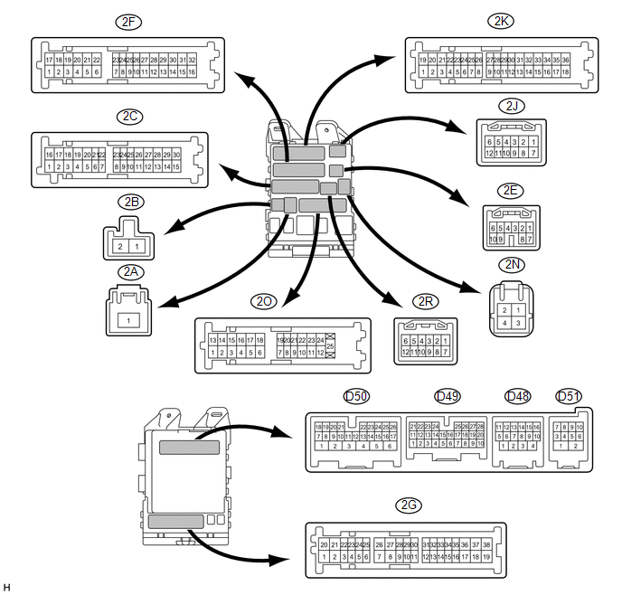
1. CHECK MAIN BODY ECU (DRIVER SIDE JUNCTION BLOCK ASSEMBLY)
(a) Disconnect the 2A and 2C main body ECU (driver side junction block) connectors.
(b) Disconnect the 2F main body ECU connector.
(c) Measure the voltage and resistance according to the value(s) in the table below.
HINT:
Measure the values on the wire harness side with the connectors disconnected.
|
Terminal No. (Symbol) |
Wiring Color |
Terminal Description |
Condition |
Specified Condition |
|---|---|---|---|---|
|
2C-24 (BECU) - Body ground |
L - Body ground |
Battery power supply |
Always |
11 to 14 V |
|
2A-1 (ACC) - Body ground |
B - Body ground |
ACC power supply |
Always |
11 to 14 V |
|
2F-16 (GND1) - Body ground |
W-B - Body ground |
Ground |
Always |
Below 1 Ω |
If the result is not as specified, there may be a malfunction in the wire harness.
(d) Reconnect the 2A and 2C main body ECU (driver side junction block assembly) connectors.
(e) Reconnect the 2F main body ECU (driver side junction block assembly) connector.
(f) Check for pulses according to the value(s) in the table below.
|
Terminal No. (Symbol) |
Wiring Color |
Terminal Description |
Condition |
Specified Condition |
|---|---|---|---|---|
|
D48-10 (LIN2) - 2F-16 (GND1) |
P - W-B |
LIN communication line |
Ignition switch ON |
Pulse generation |
If the result is not as specified, the main body ECU (driver side junction block assembly) may be malfunctioning.
2. CHECK POWER WINDOW REGULATOR MOTOR ASSEMBLY (for DRIVER SIDE)
(a) Disconnect the I4 power window regulator motor assembly (for driver side) connector.

(b) Measure the voltage and resistance according to the value(s) in the table below.
HINT:
Measure the values on the wire harness side with the connector disconnected.
|
Terminal No. (Symbol) |
Wiring Color |
Terminal Description |
Condition |
Specified Condition |
|---|---|---|---|---|
|
I4-2 (B) - I4-1 (GND) |
P - W-B |
Battery power supply |
Always |
11 to 14 V |
|
I4-1 (GND) - Body ground |
W-B - Body ground |
Ground |
Always |
Below 1 Ω |
If the result is not as specified, there may be a malfunction in the wire harness.
(c) Reconnect the I4 power window regulator motor assembly (for driver side) connector.
(d) Check for pulses according to the value(s) in the table below.
|
Terminal No. (Symbol) |
Wiring Color |
Terminal Description |
Condition |
Specified Condition |
|---|---|---|---|---|
|
I4-9 (LIN) - I4-1 (GND) |
P - W-B |
LIN communication line |
Ignition switch ON |
Pulse generation |
If the result is not as specified, the power window regulator motor assembly (for driver side) may be malfunctioning.
3. CHECK POWER WINDOW REGULATOR MOTOR ASSEMBLY (for FRONT PASSENGER SIDE)
(a) Disconnect the H4 power window regulator motor assembly (for front passenger side) connector.

(b) Measure the voltage and resistance according to the value(s) in the table below.
HINT:
Measure the values on the wire harness side with the connector disconnected.
|
Terminal No. (Symbol) |
Wiring Color |
Terminal Description |
Condition |
Specified Condition |
|---|---|---|---|---|
|
H4-2 (B) - H4-1 (GND) |
GR - W-B |
Battery power supply |
Always |
11 to 14 V |
|
H4-1 (GND) - Body ground |
W-B - Body ground |
Ground |
Always |
Below 1 Ω |
If the result is not as specified, there may be a malfunction in the wire harness.
(c) Reconnect the H4 power window regulator motor assembly (for front passenger side) connector.
(d) Check for pulses according to the value(s) in the table below.
|
Terminal No. (Symbol) |
Wiring Color |
Terminal Description |
Condition |
Specified Condition |
|---|---|---|---|---|
|
H4-9 (LIN) - H4-1 (GND) |
BR - W-B |
LIN communication line |
Ignition switch ON |
Pulse generation |
If the result is not as specified, the power window regulator motor assembly (for front passenger side) may be malfunctioning.
4. CHECK POWER WINDOW REGULATOR MOTOR ASSEMBLY (for REAR RH SIDE)
(a) Disconnect the J2 power window regulator motor assembly (for rear RH side) connector.

(b) Measure the voltage and resistance according to the value(s) in the table below.
HINT:
Measure the values on the wire harness side with the connector disconnected.
|
Terminal No. (Symbol) |
Wiring Color |
Terminal Description |
Condition |
Specified Condition |
|---|---|---|---|---|
|
J2-2 (B) - J2-1 (GND) |
Y - W-B |
Battery power supply |
Always |
11 to 14 V |
|
J2-1 (GND) - Body ground |
W-B - Body ground |
Ground |
Always |
Below 1 Ω |
If the result is not as specified, there may be a malfunction in the wire harness.
(c) Reconnect the J2 power window regulator motor assembly (for rear RH side) connector.
(d) Check for pulses according to the value(s) in the table below.
|
Terminal No. (Symbol) |
Wiring Color |
Terminal Description |
Condition |
Specified Condition |
|---|---|---|---|---|
|
J2-9 (LIN) - J2-1 (GND) |
V - W-B |
LIN communication line |
Ignition switch ON |
Pulse generation |
If the result is not as specified, the power window regulator motor assembly (for rear RH side) may be malfunctioning.
5. CHECK POWER WINDOW REGULATOR MOTOR ASSEMBLY (for REAR LH SIDE)
(a) Disconnect the K2 power window regulator motor assembly (for rear LH side) connector.

(b) Measure the voltage and resistance according to the value(s) in the table below.
HINT:
Measure the values on the wire harness side with the connector disconnected.
|
Terminal No. (Symbol) |
Wiring Color |
Terminal Description |
Condition |
Specified Condition |
|---|---|---|---|---|
|
K2-2 (B) - K2-1 (GND) |
GR - W-B |
Battery power supply |
Always |
11 to 14 V |
|
K2-1 (GND) - Body ground |
W-B - Body ground |
Ground |
Always |
Below 1 Ω |
If the result is not as specified, there may be a malfunction in the wire harness.
(c) Reconnect the K2 power window regulator motor assembly (for rear LH side) connector.
(d) Check for pulses according to the value(s) in the table below.
|
Terminal No. (Symbol) |
Wiring Color |
Terminal Description |
Condition |
Specified Condition |
|---|---|---|---|---|
|
K2-9 (LIN) - K2-1 (GND) |
LG - W-B |
LIN communication line |
Ignition switch ON |
Pulse generation |
If the result is not as specified, the power window regulator motor assembly (for rear LH side) may be malfunctioning.
6. CHECK MULTIPLEX NETWORK MASTER SWITCH ASSEMBLY
(a) Disconnect the I6 multiplex network master switch assembly connector.

(b) Measure the voltage and resistance according to the value(s) in the table below.
HINT:
Measure the values on the wire harness side with the connector disconnected.
|
Terminal No. (Symbol) |
Wiring Color |
Terminal Description |
Condition |
Specified Condition |
|---|---|---|---|---|
|
I6-11 (B) - I6-12 (E) |
GR - W-B |
Battery power supply |
Always |
11 to 14 V |
|
I6-12 (E) - Body ground |
W-B - Body ground |
Ground |
Always |
Below 1 Ω |
If the result is not as specified, there may be a malfunction in the wire harness.
(c) Reconnect the I6 multiplex network master switch assembly connector.
(d) Check for pulses according to the value(s) in the table below.
|
Terminal No. (Symbol) |
Wiring Color |
Terminal Description |
Condition |
Specified Condition |
|---|---|---|---|---|
|
I6-17 (LIN1) - I6-12 (E) |
L - W-B |
LIN communication line |
Ignition switch ON |
Pulse generation |
If the result is not as specified, the multiplex network master switch assembly may be malfunctioning.
7. CHECK SLIDING ROOF ECU (SLIDING ROOF DRIVE GEAR ASSEMBLY) [w/ Sliding Roof]
(a) Disconnect the P4 sliding roof ECU (sliding roof drive gear assembly) connector.

(b) Measure the voltage and resistance according to the value(s) in the table below.
HINT:
Measure the values on the wire harness side with the connector disconnected.
|
Terminal No. (Symbol) |
Wiring Color |
Terminal Description |
Condition |
Specified Condition |
|---|---|---|---|---|
|
P4-1 (B) - P4-2 (E) |
R - W-B |
Battery power supply |
Always |
11 to 14 V |
|
P4-2 (E) - Body ground |
W-B - Body ground |
Ground |
Always |
Below 1 Ω |
If the result is not as specified, there may be a malfunction in the wire harness.
(c) Reconnect the P4 sliding roof ECU (sliding roof drive gear assembly) connector.
(d) Check for pulses according to the value(s) in the table below.
|
Terminal No. (Symbol) |
Wiring Color |
Terminal Description |
Condition |
Specified Condition |
|---|---|---|---|---|
|
P4-4 (LIN) - P4-2 (E) |
P - W-B |
LIN communication line |
Ignition switch ON |
Pulse generation |
If the result is not as specified, the sliding roof ECU (sliding roof drive gear assembly) may be malfunctioning.
8. CHECK CERTIFICATION ECU (SMART KEY ECU ASSEMBLY) [w/ Smart Key System]
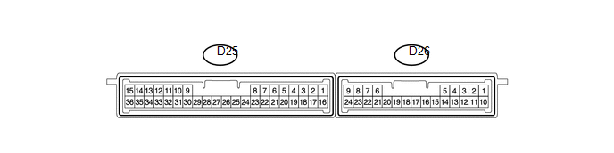
(a) Disconnect the D25 certification ECU (smart key ECU assembly) connector.
(b) Measure the voltage and resistance according to the value(s) in the table below.
HINT:
Measure the values on the wire harness side with the connector disconnected.
|
Terminal No. (Symbol) |
Wiring Color |
Terminal Description |
Condition |
Specified Condition |
|---|---|---|---|---|
|
D25-1 (+B) - D25-15 (E) |
G - B |
Battery power supply |
Always |
11 to 14 V |
|
D25-15 (E) - Body ground |
B - Body ground |
Ground |
Always |
Below 1 Ω |
If the result is not as specified, there may be a malfunction in the wire harness.
(c) Reconnect the D25 certification ECU (smart key ECU assembly) connector.
(d) Measure the voltage and check for pulses according to the value(s) in the table below.
|
Terminal No. (Symbol) |
Wiring Color |
Terminal Description |
Condition |
Specified Condition |
|---|---|---|---|---|
|
D25-16 (IG) - D25-15 (E) |
R - B |
Engine switch power supply |
Ignition switch ON |
11 to 14 V |
|
D25-16 (IG) - D25-15 (E) |
R - B |
Engine switch power supply |
Ignition switch off |
Below 1 V |
|
D25-29 (LIN) - D25-15 (E) |
P - B |
LIN communication line |
Ignition switch ON |
Pulse generation |
If the result is not as specified, the certification ECU (smart key ECU assembly) may be malfunctioning.
9. CHECK POWER MANAGEMENT CONTROL ECU (w/ Smart Key System)
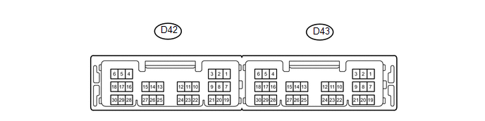
(a) Disconnect the D43 power management control ECU connector.
(b) Measure the voltage and resistance according to the value(s) in the table below.
HINT:
Measure the values on the wire harness side with the connector disconnected.
|
Terminal No. (Symbol) |
Wiring Color |
Terminal Description |
Condition |
Specified Condition |
|---|---|---|---|---|
|
D43-1 (AM22) - D43-6 (GND) |
LG - W |
Battery power supply |
Always |
11 to 14 V |
|
D43-2 (AM21) - D43-6 (GND) |
Y - W |
Battery power supply |
Always |
11 to 14 V |
|
D43-5 (GND2) - Body ground |
W-B - Body ground |
Ground |
Always |
Below 1 Ω |
|
D43-6 (GND) - Body ground |
W - Body ground |
Ground |
Always |
Below 1 Ω |
(c) Reconnect the D43 power management control ECU connector.
(d) Check for pulses according to the value(s) in the table below.
|
Terminal No. (Symbol) |
Wiring Color |
Terminal Description |
Condition |
Specified Condition |
|---|---|---|---|---|
|
D43-24 (LIN2) -D43-6 (GND) |
BR - W |
LIN communication line |
Ignition switch ON |
Pulse generation |
If the result is not as specified, the power management control ECU connector.
10. CHECK STEERING LOCK ECU (STEERING LOCK ACTUATOR ASSEMBLY) [w/ Smart Key System]
(a) Disconnect the D17 steering lock ECU (steering lock actuator assembly) connector.

(b) Measure the voltage and resistance according to the value(s) in the table below.
HINT:
Measure the values on the wire harness side with the connector disconnected.
|
Terminal No. (Symbol) |
Wiring Color |
Terminal Description |
Condition |
Specified Condition |
|---|---|---|---|---|
|
D17-1 (GND) - Body ground |
W-B - Body ground |
Ground |
Always |
Below 1 Ω |
|
D17-6 (IG2) - D17-1 (GND) |
LG - W-B |
Engine switch power supply |
Ignition switch ON |
11 to 14 V |
|
D17-6 (IG2) - D17-1 (GND) |
LG - W-B |
Engine switch power supply |
Ignition switch off |
Below 1 V |
|
D17-7 (B) - D17-1 (GND) |
P - W-B |
Battery power supply |
Always |
11 to 14 V |
If the result is not as specified, there may be a malfunction in the wire harness.
(c) Reconnect the D17 steering lock ECU (steering lock actuator assembly) connector.
(d) Check for pulses according to the value(s) in the table below.
|
Terminal No. (Symbol) |
Wiring Color |
Terminal Description |
Condition |
Specified Condition |
|---|---|---|---|---|
|
D17-5 (LIN) - D17-1 (GND) |
L - W-B |
LIN communication line |
Ignition switch ON |
Pulse generation |
If the result is not as specified, the steering lock ECU (steering lock actuator assembly) may be malfunctioning.
 Problem Symptoms Table
PROBLEM SYMPTOMS TABLE
Use the table below to help determine the cause of problem symptoms.
If multiple suspected areas are listed, the potential causes of the symptoms
are listed in o ...
 Diagnosis System
DIAGNOSIS SYSTEM
1. DESCRIPTION
The main body ECU (driver side junction block assembly) and certification ECU
(smart key ECU assembly) control the LIN communication system. LIN communication
sys ...
Other materials about Toyota Venza:
On-vehicle Inspection
ON-VEHICLE INSPECTION
PROCEDURE
1. INSPECT COMPRESSOR FOR METALLIC SOUND
(a) Check if there is abnormal metallic sound from the A/C compressor (compressor
with pulley) when the A/C switch is on and the A/C compressor (compressor with pulley)
operates.
...
Gauges and meters
►Vehicles with smart key system
The following gauges, meters and display illuminate when the “ENGINE START STOP”
switch is in IGNITION ON mode.
►Vehicles without smart key system
The following gauges, meters and displays illuminate when ...
Removal
REMOVAL
PROCEDURE
1. REMOVE UPPER CONSOLE PANEL SUB-ASSEMBLY (w/o Seat Heater System)
2. REMOVE UPPER CONSOLE PANEL SUB-ASSEMBLY (w/ Seat Heater System)
3. REMOVE NO. 2 CONSOLE BOX CARPET
(a) Remove the No. 2 console box carpet.
...

0.1219