Toyota Venza: System Diagram
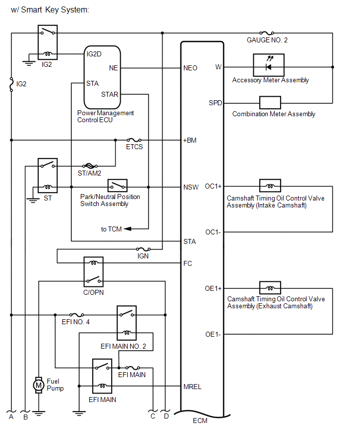
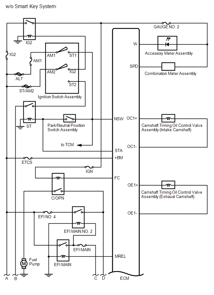
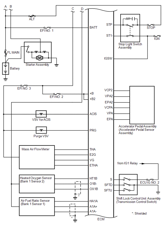
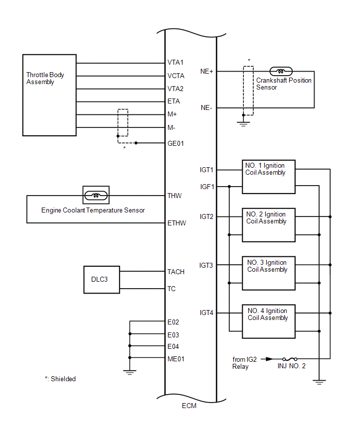
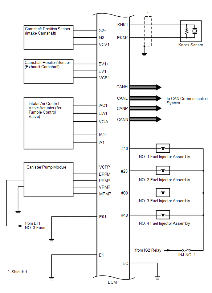
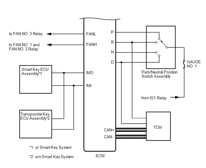
SYSTEM DIAGRAM
 How To Proceed With Troubleshooting
CAUTION / NOTICE / HINT
HINT:
*: Use the Techstream.
PROCEDURE
1.
VEHICLE BROUGHT TO WORKSHOP
NEXT
...
 Basic Inspection
BASIC INSPECTION
When the malfunction is not confirmed by the DTC check, troubleshooting should
be carried out in all circuits considered to be possible causes of the problem.
In many cases, by c ...
Other materials about Toyota Venza:
Check CAN Bus Line for Short to GND
DESCRIPTION
There may be a short circuit between the CAN bus main wire and GND when there
is no resistance between terminals 6 (CANH) and 4 (CG) or 14 (CANL) and 4 (CG) of
the DLC3.
Symptom
Trouble Area
No resistanc ...
Ignition Key Cylinder Light
Components
COMPONENTS
ILLUSTRATION
Inspection
INSPECTION
PROCEDURE
1. INSPECT TRANSPONDER KEY AMPLIFIER
(a) Connect a positive (+) lead from battery to terminal 2 and a negative
(-) lead to terminal 6.
...
Drive Belt
Components
COMPONENTS
ILLUSTRATION
On-vehicle Inspection
ON-VEHICLE INSPECTION
PROCEDURE
1. INSPECT V-RIBBED BELT
(a) Check the belt for wear, cracks or other signs of damage.
If any of the following defects is found, replace the V-r ...

0.1784