Toyota Venza: System Diagram
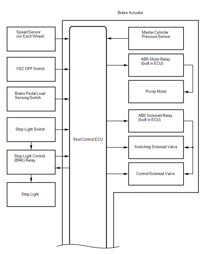
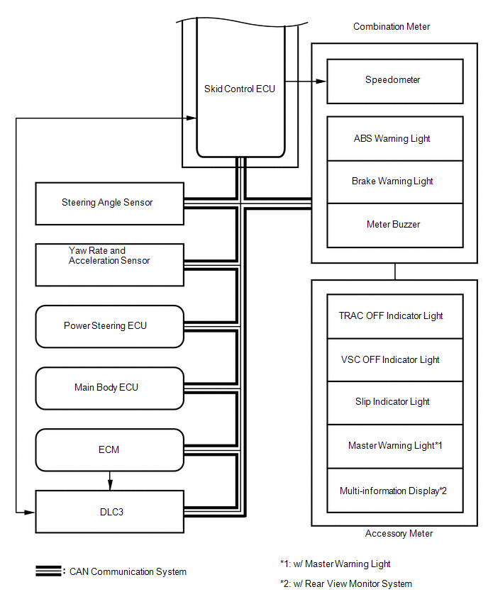
SYSTEM DIAGRAM
|
Transmitting ECU (Transmitter) |
Receiving ECU |
Signal |
Communication Method |
|---|---|---|---|
|
Skid control ECU |
Steering angle sensor |
Steering angle sensor request signal |
CAN communication system |
|
Steering angle sensor |
Skid control ECU |
Steering angle sensor signal |
CAN communication system |
|
Skid control ECU |
Yaw rate and acceleration sensor |
Yaw rate and acceleration request signal |
CAN communication system |
|
Yaw rate and acceleration sensor |
Skid control ECU |
Yaw rate and acceleration signal |
CAN communication system |
|
Skid control ECU |
ECM |
|
CAN communication system |
|
ECM |
Skid control ECU |
|
CAN communication system |
|
Skid control ECU |
Power steering ECU |
Target additional torque signal |
CAN communication system |
|
Power steering ECU |
Skid control ECU |
Electronic power steering cooperative control enabling signal |
CAN communication system |
|
Main body ECU |
Skid control ECU |
Parking brake switch signal |
CAN communication system |
|
Skid control ECU |
Combination meter |
|
CAN communication system |
 System Description
SYSTEM DESCRIPTION
1. FUNCTION DESCRIPTION
(a) Steering Cooperative Control
(1) Enhanced-VSC performs coordinated control consisting of VSC and electronic
power steering. By integrating these pre ...
 How To Proceed With Troubleshooting
CAUTION / NOTICE / HINT
HINT:
*: Use the Techstream.
PROCEDURE
1.
VEHICLE BROUGHT TO WORKSHOP
NEXT
...
Other materials about Toyota Venza:
Power windows
The power windows can be opened and closed using the following switches.
1. One-touch closing*
2. Closing
3. One-touch opening*
4. Opening
*:To stop the window partway, operate the switch in the opposite direction.
Lock switch
Press the switch down ...
Seat Heater System
Precaution
PRECAUTION
1. NOTICE FOR INITIALIZATION
HINT:
When disconnecting the cable from the negative (-) battery terminal, initialize
the following systems after the cable is reconnected.
System Name
See procedure
...
Pressure Control Solenoid "B" Electrical (Shift Solenoid Valve SL2) (P0778)
DESCRIPTION
Changing from 1st to 6th is performed by the TCM turning shift solenoid valves
SL1, SL2, SL3, SL4 and SL on and off. If an open or short circuit occurs in any
of the shift solenoid valves, the TCM controls the remaining normal shift solenoid
...

0.1601