Toyota Venza: System Diagram
SYSTEM DIAGRAM
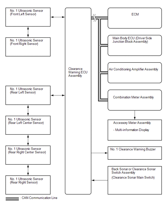 Communication Table
|
Sender |
Receiver |
Signal |
Line |
|---|---|---|---|
|
Main Body ECU (Driver Side Junction Block Assembly) |
Clearance Warning ECU Assembly |
Destination information |
CAN |
|
ECM |
Clearance Warning ECU Assembly |
Shift position |
CAN |
|
Combination Meter Assembly |
Clearance Warning ECU Assembly |
Vehicle speed |
CAN |
|
Air Conditioning Amplifier Assembly |
Clearance Warning ECU Assembly |
Ambient temperature display |
CAN |
|
Clearance Warning ECU Assembly |
Combination Meter Assembly |
|
CAN |
 System Description
SYSTEM DESCRIPTION
1. GENERAL
(a) This system uses ultrasonic sensors to detect any obstacles at the corners
and the rear of the vehicle. The system then informs the driver of the distance
betwe ...
 How To Proceed With Troubleshooting
CAUTION / NOTICE / HINT
HINT:
Use the following procedure to troubleshoot the intuitive parking assist
system.
*: Use the Techstream.
PROCEDURE
1.
VEHI ...
Other materials about Toyota Venza:
On-vehicle Inspection
ON-VEHICLE INSPECTION
CAUTION / NOTICE / HINT
HINT:
Use the same procedure for the RH side and LH side.
The procedure listed below is for the LH side.
PROCEDURE
1. REMOVE FRONT WHEEL
2. SEPARATE FRONT DISC BRAKE CALIPER ASSEMBLY
3. ...
Satellite Radio Antenna
Components
COMPONENTS
ILLUSTRATION
ILLUSTRATION
Removal
REMOVAL
PROCEDURE
1. REMOVE ROOF HEADLINING ASSEMBLY
(See page )
2. REMOVE ROOF ANTENNA POLE SUB-ASSEMBLY
3. REMOVE SATELLITE RADIO ANTENNA ASSEMBLY
(a) Disconnect the co ...
System Diagram
SYSTEM DIAGRAM
Communication Table
Sender
Receiver
Signal
Line
ECM
Navigation Receiver Assembly*1
Radio and Display Receiver Assembly*2
Reverse sig ...

0.1416