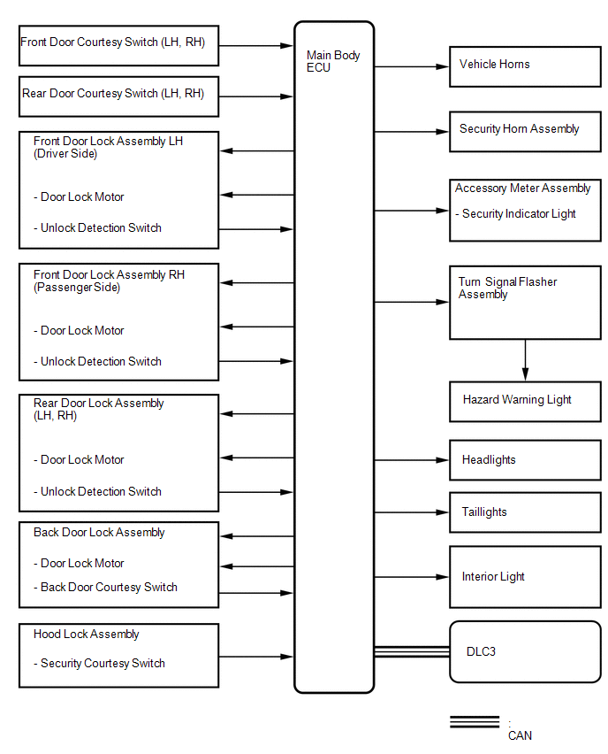
Toyota Venza: System Diagram
SYSTEM DIAGRAM
 Precaution
PRECAUTION
1. NOTICE FOR INITIALIZATION
CAUTION:
When disconnecting the cable from the negative (-) battery terminal, initialize
the following system after the cable is reconnected.
S ...
 How To Proceed With Troubleshooting
CAUTION / NOTICE / HINT
HINT:
Use this procedure to troubleshoot the theft deterrent system.
*: Use the Techstream.
PROCEDURE
1.
VEHICLE BROUGHT TO WORKSHO ...
Other materials about Toyota Venza:
Black Screen
PROCEDURE
1.
CHECK DISPLAY SETTING
(a) Check that the display is not in screen off mode.
OK:
The display setting is not in screen off mode.
NG
CHANGE SCREEN TO SCREEN ON MODE
...
Lost Communication with Rear Gate Module (U0230)
DESCRIPTION
DTC No.
DTC Detection Condition
Trouble Area
U0230
No communication from the power back door ECU (back door motor unit)
or back door closer ECU continues.
Power ...
System Diagram
SYSTEM DIAGRAM
1. CAN AND DIRECT LINE SIGNALS
2. INPUT AND OUTPUT SIGNALS OF THE ACCESSORY METER ASSEMBLY
Warning light or indicator light
Communication Signal
Receiver
Communication Line
Sender
...

0.1432