Toyota Venza: Rear Axle Hub Bolt
Components
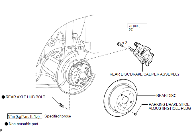
COMPONENTS
ILLUSTRATION
Replacement
REPLACEMENT
CAUTION / NOTICE / HINT
HINT:
- Use the same procedure for the RH side and LH side.
- The procedure listed below is for the LH side.
PROCEDURE
1. REMOVE REAR WHEEL
2. SEPARATE REAR DISC BRAKE CALIPER ASSEMBLY
.gif)
3. REMOVE REAR DISC
4. REMOVE REAR AXLE HUB BOLT
|
(a) Temporarily install the 2 nuts to the rear axle hub bolt as shown in the illustration. Text in Illustration
Recommended service nut: Thread diameter: 12.0 mm (0.472 in.) Thread pitch: 1.5 mm (0.0591 in.) NOTICE: Install the nuts to prevent damage to the rear axle hub bolts. |
|
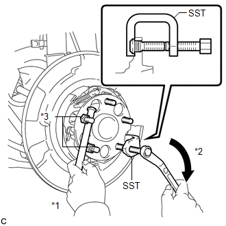
(b) Using SST and a brass bar or an equivalent tool to hold the rear axle hub and bearing assembly, remove the rear axle hub bolt.
SST: 09611-12010
NOTICE:
Do not damage the threads of the rear axle hub bolts.
5. INSTALL REAR AXLE HUB BOLT
|
(a) Temporarily install a new rear axle hub bolt to the rear axle hub and bearing assembly. |
|
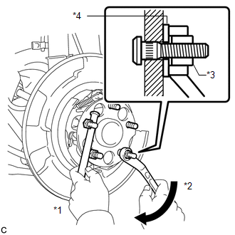
(b) Install a washer and nut to the new rear axle hub bolt as shown in the illustration.
Text in Illustration|
*1 |
Hold |
|
*2 |
Turn |
|
*3 |
Nut |
|
*4 |
Washer |
Recommended service nut:
Thread diameter: 12.0 mm (0.472 in.)
Thread pitch: 1.5 mm (0.0591 in.)
HINT:
The thickness of the washer is preferably 5 mm (0.197 in.) or more.
(c) Using a brass bar or an equivalent tool to hold the rear axle hub and bearing assembly, install the rear axle hub bolt by tightening the nut.
NOTICE:
- Install the nuts to prevent damage to the hub bolts.
- Do not damage the threads of the rear axle hub bolts.
(d) Remove the 3 nuts and washer from the 3 rear axle hub bolts.
6. INSTALL REAR DISC
7. INSTALL REAR DISC BRAKE CALIPER ASSEMBLY
8. INSTALL REAR WHEEL
Torque:
103 N·m {1050 kgf·cm, 76 ft·lbf}
 Installation
INSTALLATION
CAUTION / NOTICE / HINT
HINT:
Use the same procedure for the RH side and LH side.
The procedure listed below is for the LH side.
PROCEDURE
1. INSTALL REAR AXLE CARR ...

Other materials about Toyota Venza:
Short in Front Passenger Side Squib 2nd Step Circuit (B1815/54-B1818/54)
DESCRIPTION
The front passenger side squib 2nd step circuit consists of the center airbag
sensor assembly and front passenger airbag assembly.
The center airbag sensor assembly uses this circuit to deploy the airbag when
deployment conditions are met.
T ...
Brake Signal Malfunction (B2284)
DESCRIPTION
The power management control ECU receives brake signal information from 2 sources.
It receives a signal from the stop light switch assembly via a direct line, and
a signal from the ECM via CAN. If the information from these 2 sources is incons ...
Removal
REMOVAL
PROCEDURE
1. PRECAUTION
NOTICE:
Be sure to read Precaution thoroughly before servicing (See page
).
2. REMOVE SHIFT LEVER ASSEMBLY
(See page )
3. DISCONNECT INSTRUMENT PANEL WIRE ASSEMBLY
(a) Check that the ignition switch is off.
(b) Check ...

0.1458