Toyota Venza: System Diagram
SYSTEM DIAGRAM
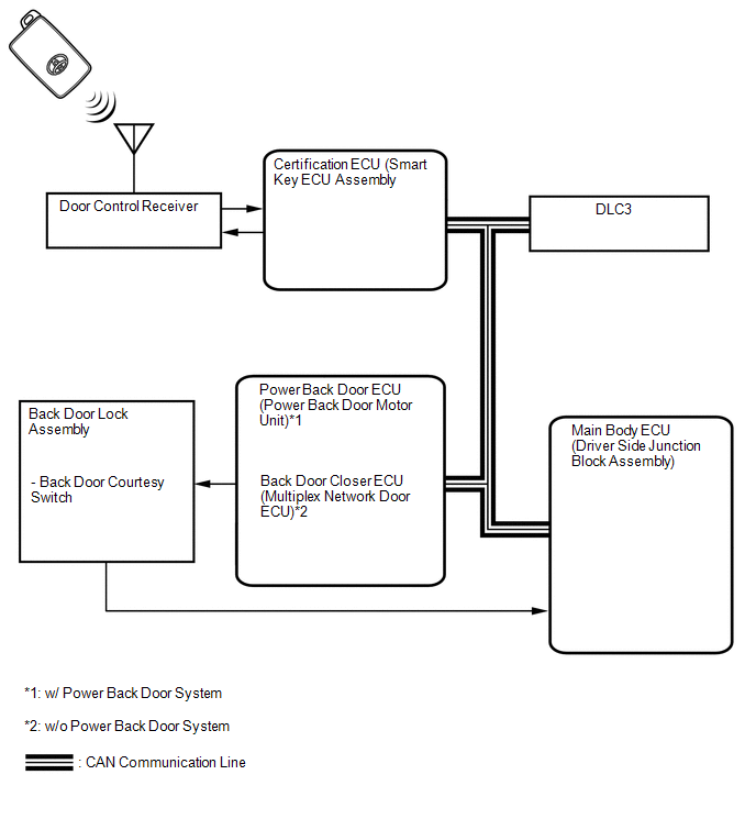
 Communication Table
|
Transmitting ECU (Transmitter) |
Receiving ECU (Receiver) |
Signal |
Line |
|---|---|---|---|
|
Certification ECU (Smart key ECU assembly) |
Main body ECU (Driver side junction block assembly) |
Wireless door lock signal |
CAN |
|
Main body ECU (Driver side junction block assembly) |
Power Back Door ECU (Power Back door motor unit)*1 Back Door Closer ECU (Multiplex Network Door ECU)*2 |
Power Back door control signal |
CAN |
- *1: w/ Power Back Door System
- *2: w/o Power Back Door System
 System Description
SYSTEM DESCRIPTION
1. WIRELESS DOOR LOCK CONTROL SYSTEM
The wireless door lock control system can be used to lock and unlock all doors
from a distance. The system is controlled by a door control t ...
 How To Proceed With Troubleshooting
CAUTION / NOTICE / HINT
HINT:
The wireless door lock control system troubleshooting procedures are
based on the premise that the power door lock control system is operating
normally. ...
Other materials about Toyota Venza:
Sliding Roof does not Move by Operating Sliding Roof Control Switch
DESCRIPTION
The sliding roof ECU (sliding roof drive gear sub-assembly) receives switch slide
and tilt signals and drives its built-in motor.
WIRING DIAGRAM
CAUTION / NOTICE / HINT
NOTICE:
Inspect the fuses for circuits related to this system ...
Transfer System
Precaution
PRECAUTION
Prior to starting any work, clean the transfer assembly to prevent sand
or mud deposits from entering the assembly.
When removing any light alloy components such as the transfer cover,
do not pry on the component wi ...
Removal
REMOVAL
PROCEDURE
1. REMOVE AIR CONDITIONING UNIT ASSEMBLY
(See page )
2. REMOVE NO. 1 FINISH PANEL MOUNTING BRACKET
3. REMOVE NO. 2 FINISH PANEL MOUNTING BRACKET
4. REMOVE NO. 3 AIR DUCT SUB-ASSEMBLY
5. REMOVE NO. 2 AIR DUCT SUB-ASSEMBLY
...

0.1376