Toyota Venza: Parts Location
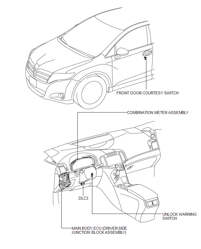
PARTS LOCATION
ILLUSTRATION
 Precaution
PRECAUTION
NOTICE:
When disconnecting the cable from the negative (-) battery terminal, initialize
the following systems after the cable is reconnected.
System Name
See Proc ...
 System Diagram
SYSTEM DIAGRAM
Communication Table
Sender
Receiver
Signal
Communication Method
Main Body ECU (Driver Side Junction Block Assembly)
...
Other materials about Toyota Venza:
Customizable features
1. Vehicles with TFT type multi-information display: Some function settings can
be changed by operating the multi-information display.
2. Settings that can be changed by your Toyota dealer
Definition of symbols: O = Available, -- = Not available
...
Cruise Control Input Circuit (P0575)
DESCRIPTION
This DTC indicates the internal abnormalities of the ECM.
DTC
DTC Detection Condition
Trouble Area
P0575
When both of the following conditions are met:
STP signals input t ...
Removal
REMOVAL
PROCEDURE
1. RECOVER REFRIGERANT FROM REFRIGERATION SYSTEM
2. DISCONNECT CABLE FROM NEGATIVE BATTERY TERMINAL
NOTICE:
When disconnecting the cable, some systems need to be initialized after the cable
is reconnected (See page ).
3. REMOVE FR ...

0.1416