Toyota Venza: System Diagram
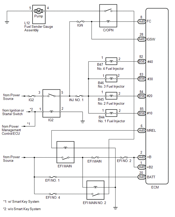
SYSTEM DIAGRAM
 On-vehicle Inspection
ON-VEHICLE INSPECTION
PROCEDURE
1. CHECK FOR FUEL PUMP OPERATION AND INSPECT FOR FUEL LEAK
(a) Check fuel pump operation.
(1) Connect the Techstream to the DLC3.
(2) Turn the ignition switch to O ...
 Fuel Tank
...
Other materials about Toyota Venza:
Inspection
INSPECTION
PROCEDURE
1. INSPECT STARTER ASSEMBLY
NOTICE:
These tests must be performed within 3 to 5 seconds to avoid burning out the
coil.
(a) Perform a pull-in test.
(1) Remove the nut and disconnect the lead wire from terminal C.
(2) Con ...
Passenger Side Buckle Switch Circuit Malfunction (B1771)
DESCRIPTION
The passenger side buckle switch circuit consists of the occupant classification
ECU and front seat inner belt assembly RH.
DTC B1771 is recorded when a malfunction is detected in the passenger side buckle
switch circuit.
Troubleshoot DTC B1 ...
Front Passenger Side Seat Belt Warning Light Malfunction
DESCRIPTION
The occupant classification ECU detects the state of the front seat inner belt
assembly RH and load sensor when the front passenger side seat is occupied with
the ignition switch ON. If the front passenger side seat belt is not fastened, the
...

0.1434