Toyota Venza: Removal
REMOVAL
CAUTION / NOTICE / HINT
HINT:
- Use the same procedure for the RH side and LH side.
- The procedure listed below is for the LH side.
PROCEDURE
1. REMOVE REAR WHEEL
2. SEPARATE REAR FLEXIBLE HOSE
.gif)
3. SEPARATE REAR DISC BRAKE CALIPER ASSEMBLY
4. REMOVE REAR DISC
5. SEPARATE REAR SPEED SENSOR WIRE
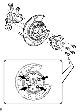
6. REMOVE REAR AXLE HUB AND BEARING ASSEMBLY
|
(a) Remove the 4 bolts and the rear axle hub and bearing assembly. NOTICE: Use wire or an equivalent tool to keep the parking brake assembly from hanging down by the parking brake cable assembly. |
|
 On-vehicle Inspection
ON-VEHICLE INSPECTION
CAUTION / NOTICE / HINT
HINT:
Use the same procedure for the RH side and LH side.
The procedure listed below is for the LH side.
PROCEDURE
1. REMOVE REAR W ...
 Installation
INSTALLATION
CAUTION / NOTICE / HINT
HINT:
Use the same procedure for the RH side and LH side.
The procedure listed below is for the LH side.
PROCEDURE
1. INSTALL REAR AXLE HUB ...
Other materials about Toyota Venza:
Components
COMPONENTS
ILLUSTRATION
ILLUSTRATION
ILLUSTRATION
ILLUSTRATION
ILLUSTRATION
...
Cooling System
On-vehicle Inspection
ON-VEHICLE INSPECTION
PROCEDURE
1. INSPECT FOR COOLANT LEAK
CAUTION:
Do not remove the radiator cap while the engine and radiator are still hot. Pressurized
hot engine coolant and steam may be released and cause serious burns.
N ...
Emission inspection and maintenance (I/M) programs
Some states have vehicle emission inspection programs which include OBD (On
Board Diagnostics) checks. The OBD system monitors the operation of the emission
control system.
- If the malfunction indicator lamp comes on
The OBD system determines that ...

0.1336