Toyota Venza: Components
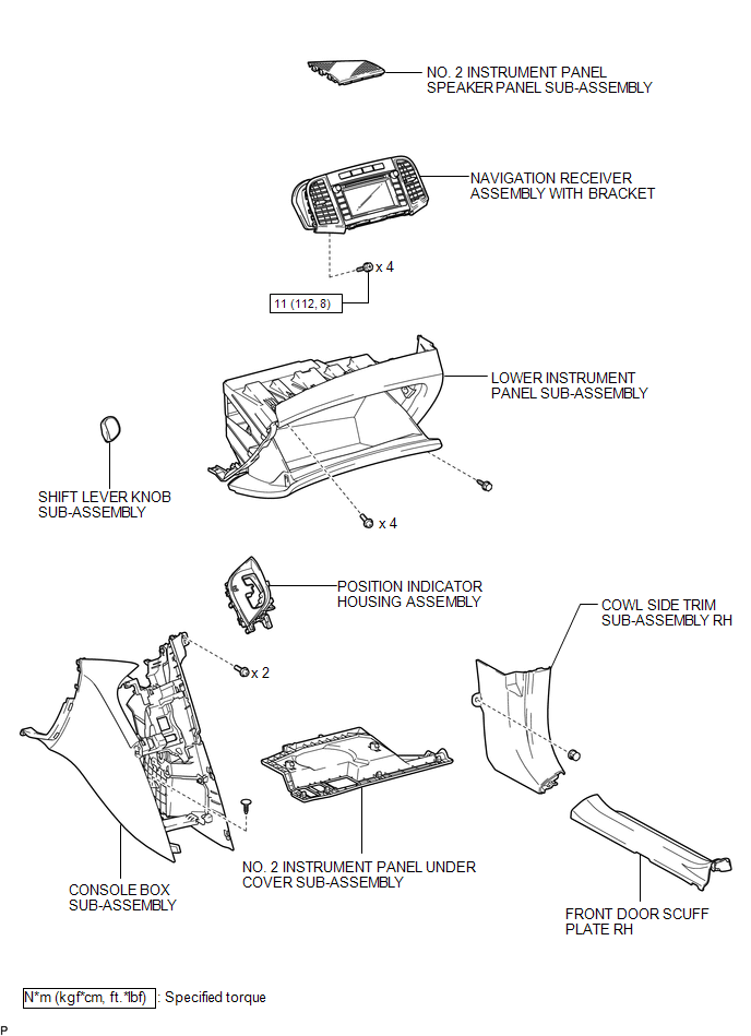
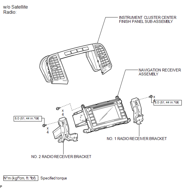
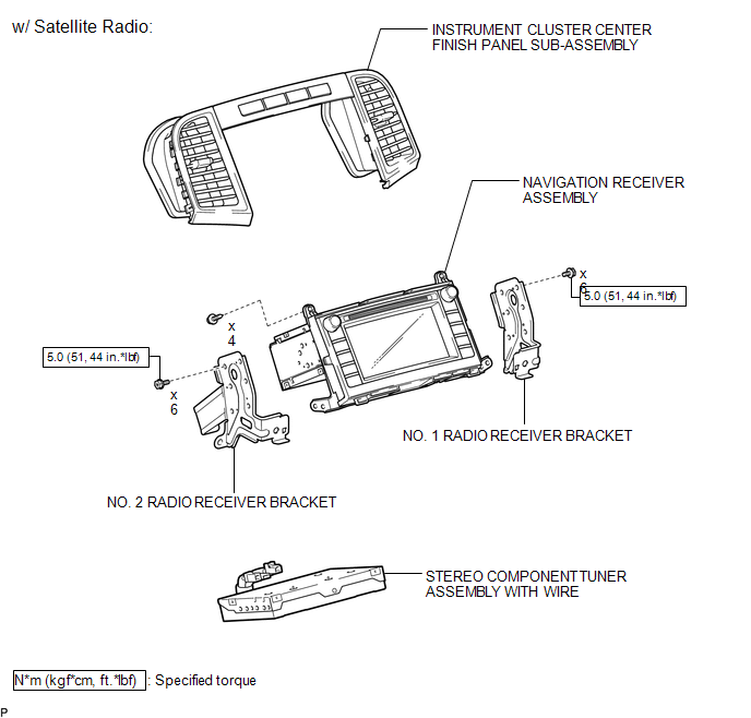
COMPONENTS
ILLUSTRATION
.png)
ILLUSTRATION
ILLUSTRATION
ILLUSTRATION

 Removal
REMOVAL
PROCEDURE
1. PRECAUTION
(See page )
NOTICE:
After turning the ignition switch off, waiting time may be required before disconnecting
the cable from the negative (-) battery terminal. T ...
Other materials about Toyota Venza:
Road Test
ROAD TEST
1. PROBLEM SYMPTOM CONFIRMATION
(a) Inspect the SET function.
Text in Illustration
*1
ON/OFF
*2
- SET
(1) Turn the cruise control main switch on.
(2) Drive at the required speed of bet ...
Door Courtesy Switch Circuit
DESCRIPTION
The main body ECU (driver side junction block assembly) detects the condition
of the door courtesy light switch.
WIRING DIAGRAM
PROCEDURE
1.
READ VALUE USING TECHSTREAM
(a) Connect the Techstream to the DLC3 ...
If the shift lever cannot be shifted from “P”
If the shift lever cannot be shifted with your foot on the brake, there may
be a problem with the shift lock system (a system to prevent accidental operation
of the shift lever). Have the vehicle inspected by your Toyota dealer immediately.
The following ...

0.133