Toyota Venza: Removal
REMOVAL
PROCEDURE
1. REMOVE UPPER CONSOLE PANEL SUB-ASSEMBLY (w/o Seat Heater System)
.gif)
2. REMOVE UPPER CONSOLE PANEL SUB-ASSEMBLY (w/ Seat Heater System)
3. REMOVE NO. 2 CONSOLE BOX CARPET
4. REMOVE CONSOLE BOX ASSEMBLY
5. REMOVE AIR CONDITIONING CONTROL ASSEMBLY
6. REMOVE FRONT DOOR SCUFF PLATE RH
7. REMOVE COWL SIDE TRIM SUB-ASSEMBLY RH
8. REMOVE NO. 2 INSTRUMENT PANEL UNDER COVER SUB-ASSEMBLY
9. REMOVE LOWER INSTRUMENT PANEL SUB-ASSEMBLY
10. REMOVE SHIFT LEVER KNOB SUB-ASSEMBLY
11. REMOVE POSITION INDICATOR HOUSING ASSEMBLY
12. REMOVE CONSOLE BOX SUB-ASSEMBLY
13. REMOVE NO. 2 INSTRUMENT PANEL SPEAKER PANEL SUB-ASSEMBLY
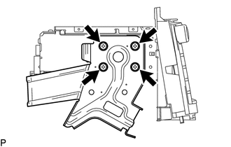
14. REMOVE RADIO AND DISPLAY RECEIVER ASSEMBLY WITH BRACKET
|
(a) Remove the 4 bolts. |
|
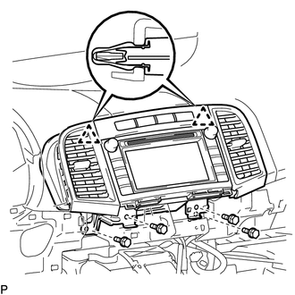
(b) Disengage the 2 clips.
(c) Disconnect each connector and remove the radio and display receiver assembly with bracket.
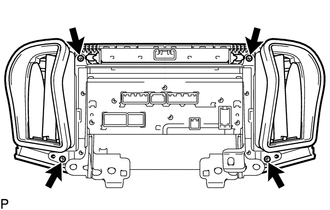
15. REMOVE INSTRUMENT CLUSTER CENTER FINISH PANEL SUB-ASSEMBLY
|
(a) Remove the 4 screws. |
|
|
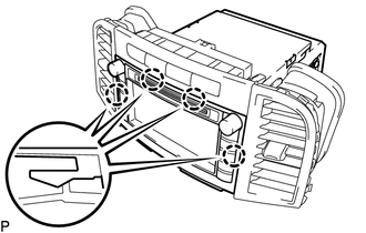
(b) Disengage the 4 claws and remove the instrument cluster center finish panel sub-assembly. |
|
16. REMOVE STEREO COMPONENT TUNER ASSEMBLY WITH WIRE (w/ Satellite Radio)
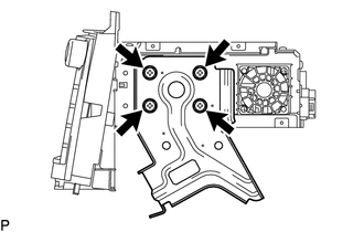
17. REMOVE NO. 1 RADIO RECEIVER BRACKET
|
(a) Remove the 4 screws and No. 1 radio receiver bracket. |
|
18. REMOVE NO. 2 RADIO RECEIVER BRACKET
|
(a) Remove the 4 screws and No. 2 radio receiver bracket. |
|
19. REMOVE RADIO AND DISPLAY RECEIVER ASSEMBLY
 Components
COMPONENTS
ILLUSTRATION
ILLUSTRATION
ILLUSTRATION
ILLUSTRATION
...
 Installation
INSTALLATION
PROCEDURE
1. INSTALL RADIO AND DISPLAY RECEIVER ASSEMBLY
2. INSTALL NO. 2 RADIO RECEIVER BRACKET
(a) Install the No. 2 radio receiver bracket with the 4 screws.
Torque:
5.0 N·m {5 ...
Other materials about Toyota Venza:
Installation
INSTALLATION
PROCEDURE
1. INSTALL FRONT DOOR BELT MOULDING
(a) Engage the 5 claws to install the front door belt moulding.
(b) Install the clip.
2. INSTALL FRONT DOOR GLASS RUN
3. INSTALL FRONT ...
Installation
INSTALLATION
PROCEDURE
1. REPAIR INSTRUCTION
2. INSTALL REAR DOOR LOWER OUTSIDE STRIPE
(a) Refer to the illustration to position the rear door lower outside stripe.
Standard Measurement
Dimension
Measurement
A
...
Does not Play even after Bluetooth Audio Mode is Selected
CAUTION / NOTICE / HINT
HINT:
Even if the portable player can play audio content, it may not be able to play
via the in-vehicle device. This does not necessarily indicate a malfunction of the
in-vehicle device.
PROCEDURE
1.
CHECK ...

0.1311