Toyota Venza: Removal
REMOVAL
PROCEDURE
1. PRECAUTION
CAUTION:
Be sure to read Precaution thoroughly before servicing (See page
.gif) ).
).
2. TURN FRONT WHEELS TO FACE STRAIGHT AHEAD
3. DISCONNECT CABLE FROM NEGATIVE BATTERY TERMINAL
CAUTION:
Wait at least 90 seconds after disconnecting the cable from the negative (-) battery terminal to disable the SRS system.
NOTICE:
When disconnecting the cable, some systems need to be initialized after the cable
is reconnected (See page ).
4. REMOVE LOWER NO. 3 STEERING WHEEL COVER
5. REMOVE LOWER NO. 2 STEERING WHEEL COVER
6. REMOVE STEERING PAD
7. REMOVE STEERING WHEEL ASSEMBLY
8. REMOVE LOWER STEERING COLUMN COVER
9. REMOVE UPPER STEERING COLUMN COVER
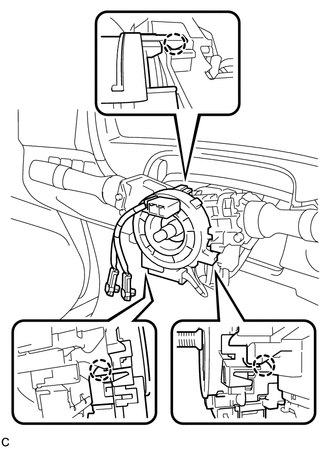
10. REMOVE SPIRAL CABLE WITH SENSOR SUB-ASSEMBLY
NOTICE:
- Do not replace the spiral cable with the battery connected and the ignition switch on (IG).
- Do not rotate the spiral cable with the battery connected and the ignition switch on (IG).
- Ensure that the steering wheel is installed and aligned straight when inspecting the steering sensor.
- Do not remove the steering sensor from the spiral cable.
(a) Disconnect the connectors from the spiral cable with sensor sub-assembly.
NOTICE:
When disconnecting any airbag connector, take care not to damage the airbag wire harness.
|
(b) Disengage the 3 claws to remove the spiral cable with sensor sub-assembly. |
|
 Inspection
INSPECTION
PROCEDURE
1. INSPECT SPIRAL CABLE
(a) Visually check for defects with the spiral cable removed from the vehicle.
(1) The defects are as follows:
Scratches on the spiral cable
...
 Installation
INSTALLATION
PROCEDURE
1. INSTALL SPIRAL CABLE WITH SENSOR SUB-ASSEMBLY
NOTICE:
Do not replace the spiral cable with the battery connected and the ignition
switch on (IG).
Do not r ...
Other materials about Toyota Venza:
Light Control Switch Circuit
DESCRIPTION
The main body ECU (driver side junction block assembly) receives the following
switch information:
Light control switch position off, tail, head or AUTO
Dimmer switch position high, low or high flash (pass)
Fog light switch posit ...
Installation
INSTALLATION
CAUTION / NOTICE / HINT
NOTICE:
When disconnecting the steering intermediate shaft assembly and pinion shaft
of steering gear assembly, be sure to place matchmarks before servicing.
PROCEDURE
1. INSTALL TIE ROD ASSEMBLY LH
(a) I ...
How To Proceed With Troubleshooting
CAUTION / NOTICE / HINT
HINT:
*: Use the Techstream.
PROCEDURE
1.
VEHICLE BROUGHT TO WORKSHOP
NEXT
2.
CUSTOMER PROBLEM ANALYSIS
...

0.1371