Toyota Venza: Installation
INSTALLATION
PROCEDURE
1. INSTALL SPIRAL CABLE WITH SENSOR SUB-ASSEMBLY
NOTICE:
- Do not replace the spiral cable with the battery connected and the ignition switch on (IG).
- Do not rotate the spiral cable with the battery connected and the ignition switch on (IG).
- Ensure that the steering wheel is installed and aligned straight when inspecting the steering sensor.
- Do not remove the steering sensor from the spiral cable.
(a) Check that the front wheels are facing straight ahead.
(b) Set the turn signal switch to the neutral position.
NOTICE:
If it is not in the neutral position, the turn signal switch pin may snap.
|
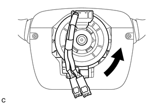
(c) Install the spiral cable with sensor sub-assembly with the 3 claws. NOTICE: When replacing the spiral cable with sensor sub-assembly with a new one, remove the lock pin before installing the steering wheel assembly. |
|
.png)
(d) Connect the connectors to the spiral cable with sensor sub-assembly.
NOTICE:
When connecting any airbag connector, take care not to damage the airbag wire harness.
2. INSTALL UPPER STEERING COLUMN COVER
.gif)
3. INSTALL LOWER STEERING COLUMN COVER
4. TURN FRONT WHEELS TO FACE STRAIGHT AHEAD
5. ADJUST SPIRAL CABLE
(a) Check that the ignition switch is off.
(b) Check that the cable is disconnected from the negative (-) battery terminal.
CAUTION:
Wait at least 90 seconds after disconnecting the cable from the negative (-) battery terminal to disable the SRS system.
|
(c) Rotate the spiral cable counterclockwise slowly by hand until it stops. NOTICE: Do not turn the spiral cable using the airbag wire harness. |
|
|
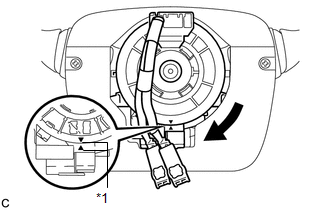
(d) Rotate the spiral cable clockwise approximately 2.5 turns to align the alignment marks. Text in Illustration
NOTICE: Do not turn the spiral cable using the airbag wire harness. HINT: The spiral cable will rotate approximately 2.5 turns to both the left and right from the center. |
|
6. INSTALL STEERING WHEEL ASSEMBLY
7. INSTALL STEERING PAD
8. INSTALL LOWER NO. 3 STEERING WHEEL COVER
9. INSTALL LOWER NO. 2 STEERING WHEEL COVER
10. INSPECT STEERING WHEEL CENTER POINT
11. CONNECT CABLE TO NEGATIVE BATTERY TERMINAL
NOTICE:
When disconnecting the cable, some systems need to be initialized after the cable
is reconnected (See page ).
12. INSPECT STEERING PAD
13. PERFORM DIAGNOSTIC SYSTEM CHECK
(a) Perform a diagnostic system check (See page
).
14. INSPECT SRS WARNING LIGHT
(a) Inspect the SRS warning light (See page
).
 Removal
REMOVAL
PROCEDURE
1. PRECAUTION
CAUTION:
Be sure to read Precaution thoroughly before servicing (See page
).
2. TURN FRONT WHEELS TO FACE STRAIGHT AHEAD
3. DISCONNECT CABLE FROM NEGATIVE BATTE ...
 Steering Pad
...
Other materials about Toyota Venza:
Chassis
General Maintenance
GENERAL MAINTENANCE
PROCEDURE
1. INSPECT STEERING LINKAGE AND GEAR HOUSING
(a) Check the steering wheel free play (See page
).
(b) Check the steering linkage for looseness or damage.
(1) Check that the tie rod ends do not have any ...
Tire information
Typical tire symbols
►Standard tire
►Compact spare tire
1. Tire size
2. DOT and Tire Identification Number (TIN)
3. Location of treadwear indicators
4. Tire ply composition and materials Plies are layers of rubber-coated parallel
cords ...
Installation
INSTALLATION
PROCEDURE
1. INSTALL NO. 1 COOLER THERMISTOR
2. INSTALL COOLER EVAPORATOR SUB-ASSEMBLY
3. INSTALL BLOWER ASSEMBLY WITH COOLER EVAPORATOR SUB-ASSEMBLY
(a) Engage the 5 claws.
(b) Engage the guide and connect the wire harness.
(c) Insta ...

0.1674