Toyota Venza: Charge Warning Light Comes ON while Driving
PROCEDURE
|
1. |
CHECK LOCK FUNCTION OF GENERATOR CLUTCH PULLEY |
(a) Check the lock function with the pulley installed in the vehicle.
(1) Visually check that the rotor in the generator operates with the engine running.
(b) Check the lock function with the pulley removed from the vehicle.
(1) Remove the generator pulley cap.
|
(2) Hold the generator rotor using SST, and turn the clutch pulley clockwise
to check that the outer ring locks (See page
Text in Illustration
OK: The outer ring locks. |
|
.gif) ).
).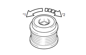
SST: 09820-63021
| NG | .gif) |
REPLACE GENERATOR CLUTCH PULLEY |
|
.gif)
|
2. |
CHECK INSTALLATION OF GENERATOR CLUTCH PULLEY |
(a) Start the engine and visually check the clutch pulley for looseness.
OK:
The clutch pulley is not loose.
| OK | |
REPLACE GENERATOR ASSEMBLY |
| NG | |
TIGHTEN GENERATOR CLUTCH PULLEY TO THE SPECIFIED TORQUE |
 Problem Symptoms Table
PROBLEM SYMPTOMS TABLE
Use the table below to help determine the cause of problem symptoms.
If multiple suspected areas are listed, the potential causes of the symptoms
are listed in o ...
 On-vehicle Inspection
ON-VEHICLE INSPECTION
PROCEDURE
1. CHECK BATTERY CONDITION
NOTICE:
If the battery is weak or if the engine is difficult to start, perform the following
procedure.
(a) Check the battery for dama ...
Other materials about Toyota Venza:
Reassembly
REASSEMBLY
PROCEDURE
1. INSTALL AIR OUTLET CONTROL SERVO MOTOR SUB-ASSEMBLY
(a) Check that the slots, links and gears of the air outlet control servo
motor sub-assembly are positioned in the correct orientation as shown in
the illustratio ...
Audio Receiver Assembly Communication Stop Mode
DESCRIPTION
Detection Item
Symptom
Trouble Area
Audio Receiver Assembly Communication Stop Mode
"Display and Navigation (AVN1)" is not displayed on the "CAN
Bus Check ...
Brake Warning Light Remains ON
DESCRIPTION
The skid control ECU is connected to the combination meter via CAN communication.
If any of the following is detected, the brake warning light remains on:
The skid control ECU connector is disconnected from the skid control
ECU.
T ...

0.1459