Toyota Venza: Removal
REMOVAL
PROCEDURE
1. RECOVER REFRIGERANT FROM REFRIGERATION SYSTEM
.gif)
2. DISCONNECT CABLE FROM NEGATIVE BATTERY TERMINAL
NOTICE:
When disconnecting the cable, some systems need to be initialized after the cable
is reconnected (See page ).
3. REMOVE FRONT WHEEL RH
4. REMOVE NO. 1 ENGINE UNDER COVER
5. SEPARATE FRONT FENDER LINER RH
6. REMOVE FRONT FENDER APRON SEAL RH
7. REMOVE V-RIBBED BELT
8. REMOVE RADIATOR ASSEMBLY
HINT:
Refer to the procedure for Remove Radiator Assembly (See page
).
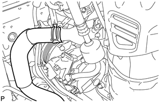
9. DISCONNECT COOLER REFRIGERANT DISCHARGE HOSE
|
(a) Disengage each clamp. |
|
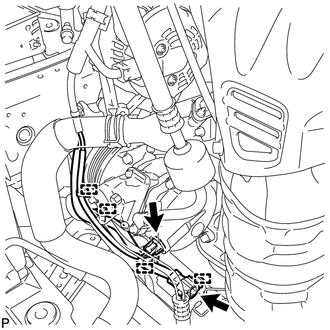
(b) Disconnect each connector.
|
(c) Using pliers, grip the claws of the clip and slide the clip to remove the No. 2 radiator hose. |
|
|
(d) Remove the bolt and disconnect the cooler refrigerant discharge hose from the compressor assembly with pulley. |
|
(e) Remove the O-ring from the discharge hose.
NOTICE:
Seal the openings of the disconnected parts using vinyl tape to prevent entry of moisture and foreign matter.
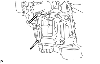
10. DISCONNECT SUCTION HOSE SUB-ASSEMBLY
|
(a) Remove the bolt and disconnect the suction hose sub-assembly from the compressor assembly with pulley. |
|
(b) Remove the O-ring from the suction hose sub-assembly.
NOTICE:
Seal the openings of the disconnected parts using vinyl tape to prevent entry of moisture and foreign matter.
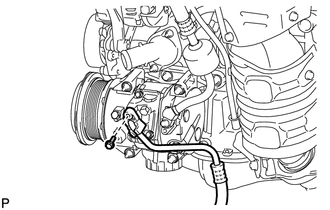
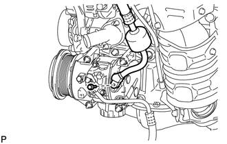
11. REMOVE COMPRESSOR ASSEMBLY WITH PULLEY
|
(a) Remove the 2 bolts, 2 nuts and compressor assembly with pulley. |
|
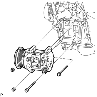
|
(b) Using an E8 "TORX" socket wrench, remove the 2 stud bolts. |
|
 Inspection
INSPECTION
PROCEDURE
1. INSPECT COMPRESSOR WITH PULLEY (SOLENOID VALVE)
(a) Measure the resistance according to the value(s) in the table below.
Standard Resistance:
...
 Installation
INSTALLATION
PROCEDURE
1. ADJUST COMPRESSOR OIL LEVEL
(a) When replacing the cooler compressor assembly with a new one, gradually
discharge the inert gas (helium) from the service va ...
Other materials about Toyota Venza:
Occupant Classification System Malfunction (B1650/32)
DESCRIPTION
The occupant classification system circuit consists of the center airbag sensor
assembly and occupant classification system.
If the center airbag sensor assembly receives signals from the occupant classification
ECU, it determines whether the ...
Unlock Warning Switch Circuit
DESCRIPTION
The key unlock warning switch assembly turns on when the ignition key is inserted
into the ignition key cylinder and turns off when the ignition key is removed.
The main body ECU (driver side junction block assembly) operates the key confinemen ...
Data List / Active Test
DATA LIST / ACTIVE TEST
1. DATA LIST
HINT:
Using the Techstream to read the Data List allows the values or states of switches,
sensors, actuators and other items to be read without removing any parts. This non-intrusive
inspection can be very useful bec ...

0.1649