Toyota Venza: Removal
REMOVAL
PROCEDURE
1. DISCONNECT CABLE FROM NEGATIVE BATTERY TERMINAL
NOTICE:
When disconnecting the cable, some systems need to be initialized after the cable
is reconnected (See page .gif) ).
).
2. REMOVE COOL AIR INTAKE DUCT SEAL
3. REMOVE NO. 1 ENGINE COVER SUB-ASSEMBLY
4. REMOVE BATTERY
5. REMOVE INLET AIR CLEANER ASSEMBLY
6. REMOVE STARTER ASSEMBLY
|
(a) Disconnect the starter connector. |
|
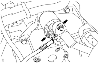
(b) Open the terminal cap, remove the nut and disconnect the starter wire.
|
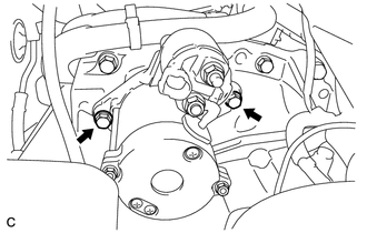
(c) Remove the 2 bolts and starter. |
|
 Components
COMPONENTS
ILLUSTRATION
ILLUSTRATION
...
 Disassembly
DISASSEMBLY
PROCEDURE
1. REMOVE MAGNETIC SWITCH ASSEMBLY
(a) Remove the nut and disconnect the lead wire from the magnetic switch.
...
Other materials about Toyota Venza:
Slide Sensor Malfunction (B2650)
DESCRIPTION
When the position control ECU and switch assembly does not receive a sensor signal
despite forward or backward movement of seat by power seat motor operation, this
DTC is output.
DTC Code
DTC Detection Condition
...
Transmission Wire(when Not Using The Engine Support Bridge)
Components
COMPONENTS
ILLUSTRATION
Installation
INSTALLATION
PROCEDURE
1. INSTALL TRANSMISSION WIRE
(a) Coat the O-ring with ATF.
(b) Coat the bolt with ATF.
(c) Install the tr ...
How To Proceed With Troubleshooting
CAUTION / NOTICE / HINT
HINT:
Use the following procedure to troubleshoot the lighting system.
*: Use the Techstream.
PROCEDURE
1.
VEHICLE BROUGHT TO WORKSHOP
NEXT
...

0.1539