Toyota Venza: Components
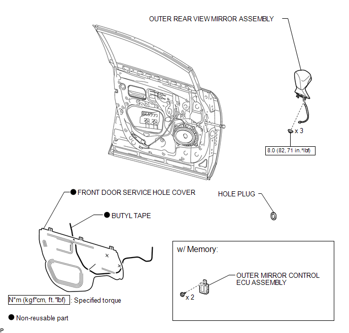
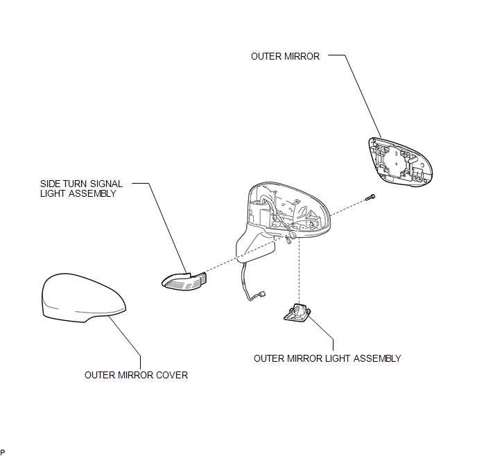
COMPONENTS
ILLUSTRATION
.png)
ILLUSTRATION
ILLUSTRATION

 Removal
REMOVAL
PROCEDURE
1. PRECAUTION
NOTICE:
After turning the ignition switch off, waiting time may be required before disconnecting
the cable from the negative (-) battery terminal. Therefore, make ...
Other materials about Toyota Venza:
Relay
On-vehicle Inspection
ON-VEHICLE INSPECTION
PROCEDURE
1. REMOVE STOP LIGHT CONTROL (BRK) RELAY
(a) Remove the stop light control (BRK) relay.
(b) Measure the resistance according to the value(s) in the table below.
Standard Resistance:
...
Front Occupant Classification Sensor LH Collision Detection (B1785)
DESCRIPTION
DTC B1785 is output when the occupant classification ECU receives a collision
detection signal sent by the front occupant classification sensor LH if an accident
occurs.
DTC B1785 is also output when the front seat assembly RH is subjected to ...
Check CAN Bus Lines for Short Circuit
DESCRIPTION
There may be a short circuit in the CAN bus main wire and/or CAN branch wire
when the resistance between terminals 6 (CANH) and 14 (CANL) of the DLC3 is below
54 Ω.
Symptom
Trouble Area
Resistance betwe ...

0.1697