Toyota Venza: Removal
REMOVAL
PROCEDURE
1. REMOVE FRONT SEAT ASSEMBLY LH
(See page .gif) )
)
2. REMOVE FRONT DOOR SCUFF PLATE LH
3. REMOVE COWL SIDE TRIM SUB-ASSEMBLY LH
4. REMOVE FRONT DOOR OPENING TRIM WEATHERSTRIP LH
5. REMOVE REAR DOOR SCUFF PLATE LH
6. REMOVE REAR DOOR OPENING TRIM WEATHERSTRIP LH
7. REMOVE LAP BELT OUTER ANCHOR COVER LH
8. DISCONNECT FRONT SEAT OUTER BELT ASSEMBLY LH
9. REMOVE LOWER CENTER PILLAR GARNISH LH
10. REMOVE TONNEAU COVER ASSEMBLY (w/ Tonneau Cover)
11. REMOVE DECK BOARD ASSEMBLY
12. REMOVE NO. 3 DECK BOARD SUB-ASSEMBLY
13. REMOVE DECK SIDE TRIM BOX LH
14. REMOVE NO. 2 DECK BOARD SUB-ASSEMBLY
15. REMOVE DECK SIDE TRIM BOX RH
16. REMOVE NO. 1 DECK BOARD
17. REMOVE REAR SEAT SUB FLOOR PANEL ASSEMBLY
18. REMOVE REAR FLOOR FINISH PLATE
19. REMOVE REAR SEAT HEADREST ASSEMBLY LH
20. REMOVE REAR SEAT INNER TRACK BRACKET COVER LH
21. REMOVE REAR SEAT OUTER TRACK BRACKET COVER LH
22. DISCONNECT REAR SEAT NO. 2 RECLINING CONTROL CABLE SUB-ASSEMBLY
23. REMOVE REAR SEAT ASSEMBLY LH
24. REMOVE RECLINING REMOTE CONTROL BEZEL LH
25. REMOVE LUGGAGE HOLD BELT STRIKER ASSEMBLY LH
26. DISCONNECT REAR SEAT OUTER BELT ASSEMBLY LH
27. REMOVE DECK TRIM SIDE PANEL ASSEMBLY LH
28. DISCONNECT FUEL LID LOCK OPEN LEVER SUB-ASSEMBLY
|
(a) Remove the bolt. |
|
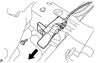
(b) Disconnect the fuel lid lock open lever sub-assembly as shown in the illustration.
|
(c) Disconnect the fuel lid lock control cable sub-assembly. |
|
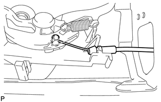
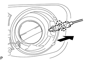
29. REMOVE FUEL LID LOCK CONTROL CABLE SUB-ASSEMBLY
|
(a) Disengage the 2 claws and disconnect the fuel lid lock control cable sub-assembly. |
|
(b) Disengage the 8 clamps and remove the fuel lid lock control cable sub-assembly.
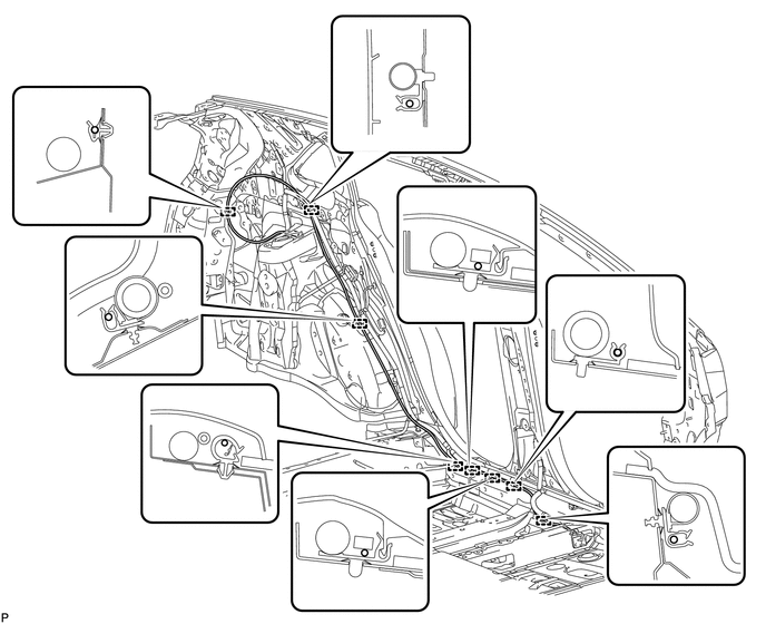
 Components
COMPONENTS
ILLUSTRATION
ILLUSTRATION
ILLUSTRATION
ILLUSTRATION
ILLUSTRATION
...
 Installation
INSTALLATION
PROCEDURE
1. INSTALL FUEL LID LOCK CONTROL CABLE SUB-ASSEMBLY
(a) Engage the 8 clamps.
(b) Engage the 2 claws and connect the fuel lid lock control cable sub-assembly.
...
Other materials about Toyota Venza:
Inspection
INSPECTION
PROCEDURE
1. INSPECT REAR STABILIZER LINK ASSEMBLY
(a) Move the ball joint stud back and forth 5 times before installing
the nut as shown in the illustration.
(b) Using a torque wrenc ...
Installation
INSTALLATION
PROCEDURE
1. INSTALL NO. 1 COOLER THERMISTOR
2. INSTALL COOLER EVAPORATOR SUB-ASSEMBLY
3. INSTALL BLOWER ASSEMBLY WITH COOLER EVAPORATOR SUB-ASSEMBLY
(a) Engage the 5 claws.
(b) Engage the guide and connect the wire harness.
(c) Insta ...
Fail-safe Chart
FAIL-SAFE CHART
1. FAIL-SAFE OPERATION
If there is a problem with sensor signals or actuator systems, the skid
control ECU prohibits power supply to the brake actuator assembly and informs
the ECM of VSC system malfunction.
The brake actuat ...

0.1725