
Toyota Venza: Installation
INSTALLATION
PROCEDURE
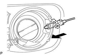
1. INSTALL FUEL LID LOCK CONTROL CABLE SUB-ASSEMBLY
(a) Engage the 8 clamps.
.png)
|
(b) Engage the 2 claws and connect the fuel lid lock control cable sub-assembly. |
|
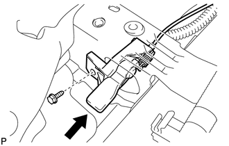
2. INSTALL FUEL LID LOCK OPEN LEVER SUB-ASSEMBLY
|
(a) Connect the fuel lid lock control cable sub-assembly. |
|
.png)
|
(b) Install the fuel lid lock open lever sub-assembly with the bolt. Torque: 5.5 N·m {56 kgf·cm, 49 in·lbf} |
|
3. INSTALL DECK TRIM SIDE PANEL ASSEMBLY LH
.gif)
4. CONNECT REAR SEAT OUTER BELT ASSEMBLY LH
5. INSTALL LUGGAGE HOLD BELT STRIKER ASSEMBLY LH
6. INSTALL RECLINING REMOTE CONTROL BEZEL LH
7. INSTALL REAR SEAT ASSEMBLY LH
8. CONNECT REAR SEAT NO. 2 RECLINING CONTROL CABLE SUB-ASSEMBLY
9. INSTALL REAR SEAT OUTER TRACK BRACKET COVER LH
10. INSTALL REAR SEAT INNER TRACK BRACKET COVER LH
11. INSTALL REAR SEAT HEADREST ASSEMBLY LH
12. INSTALL REAR FLOOR FINISH PLATE
13. INSTALL REAR SEAT SUB FLOOR PANEL ASSEMBLY
14. INSTALL NO. 1 DECK BOARD
15. INSTALL DECK SIDE TRIM BOX LH
16. INSTALL NO. 3 DECK BOARD SUB-ASSEMBLY
17. INSTALL DECK SIDE TRIM BOX RH
18. INSTALL NO. 2 DECK BOARD SUB-ASSEMBLY
19. INSTALL DECK BOARD ASSEMBLY
20. INSTALL TONNEAU COVER ASSEMBLY (w/ Tonneau Cover)
21. INSTALL LOWER CENTER PILLAR GARNISH LH
22. CONNECT FRONT SEAT OUTER BELT ASSEMBLY LH
23. INSTALL LAP BELT OUTER ANCHOR COVER LH
24. INSTALL REAR DOOR OPENING TRIM WEATHERSTRIP LH
25. INSTALL REAR DOOR SCUFF PLATE LH
26. INSTALL FRONT DOOR OPENING TRIM WEATHERSTRIP LH
27. INSTALL COWL SIDE TRIM SUB-ASSEMBLY LH
28. INSTALL FRONT DOOR SCUFF PLATE LH
29. INSTALL FRONT SEAT ASSEMBLY LH
(See page )
 Removal
REMOVAL
PROCEDURE
1. REMOVE FRONT SEAT ASSEMBLY LH
(See page )
2. REMOVE FRONT DOOR SCUFF PLATE LH
3. REMOVE COWL SIDE TRIM SUB-ASSEMBLY LH
4. REMOVE FRONT DOOR OPENING TRIM WEATHERSTRIP ...
 Hood
Hood
...
Other materials about Toyota Venza:
Microphone Circuit between Microphone and Radio Receiver
DESCRIPTION
The radio and display receiver assembly and inner rear view mirror assembly (amplifier
microphone assembly) are connected to each other using the microphone connection
detection signal lines.
Using this circuit, the radio and display receiver ...
Adjustment
ADJUSTMENT
PROCEDURE
1. INSPECT SHIFT LEVER POSITION
(a) When moving the lever from P to R with the ignition switch ON and the brake
pedal depressed, make sure that the shift lever moves smoothly and moves correctly
into position.
(b) Start the engine ...
Wireless Transmitter Memory Function does not Operate
DESCRIPTION
Key IDs can be registered (linked) with either the M1 or M2 seat memory switches.
The key ID registration procedure should be performed while the electrical key transmitter
sub-assembly or door control transmitter assembly is in the vehicle, t ...

0.1142