Toyota Venza: Removal
REMOVAL
PROCEDURE
1. REMOVE WHEEL ASSEMBLY
2. REMOVE TIRE PRESSURE WARNING VALVE AND TRANSMITTER
(a) Remove the tire valve cap.
NOTICE:
Keep the removed tire valve cap.
(b) Remove the valve core to release the air from the tire.
NOTICE:
Make sure that a sufficient amount of air has been released.
(c) Remove the nut and washer.
(d) Drop the tire pressure warning valve and transmitter with grommet into the tire.
HINT:
The grommet may remain attached to the rim.
|
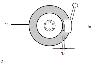
(e) Using a tire remover, remove the tire from the disc wheel. Text in Illustration
NOTICE:
|
|
(f) Take out the tire pressure warning valve and transmitter with grommet from the tire.
(g) Remove the grommet from the tire pressure warning valve and transmitter.
 Components
COMPONENTS
ILLUSTRATION
...
 Installation
INSTALLATION
CAUTION / NOTICE / HINT
NOTICE:
Always use a new grommet and valve core when installing the tire pressure
warning valve and transmitter.
Check that the washer and nut a ...
Other materials about Toyota Venza:
TC and CG Terminal Circuit
DESCRIPTION
Connecting terminals TC and CG of the DLC3 causes the system to enter self-diagnostic
mode. If a malfunction is present, the MIL will blink.
HINT:
When a particular warning light remains blinking, a ground short in the wiring
of terminal TC ...
Stereo Jack Adapter Assembly
Components
COMPONENTS
ILLUSTRATION
Removal
REMOVAL
PROCEDURE
1. REMOVE UPPER CONSOLE PANEL SUB-ASSEMBLY (w/o Seat Heater System)
2. REMOVE UPPER CONSOLE PANEL SUB-ASSEMBLY (w/ Seat Heater System)
3. REMOVE NO. 2 CONSOLE BOX CARPET
4. RE ...
Installation
INSTALLATION
PROCEDURE
1. REPAIR INSTRUCTION
2. INSTALL REAR DOOR LOWER OUTSIDE STRIPE
(a) Refer to the illustration to position the rear door lower outside stripe.
Standard Measurement
Dimension
Measurement
A
...

0.1599