Toyota Venza: Removal
REMOVAL
PROCEDURE
1. REMOVE ENGINE ASSEMBLY WITH TRANSAXLE (for 2GR-FE)
HINT:
Refer to the procedure up to Remove Engine Assembly with Transaxle (See page
.gif) ).
).
2. REMOVE ENGINE ASSEMBLY WITH TRANSAXLE (for 1AR-FE)
HINT:
Refer to the procedure up to Remove Engine Assembly with Transaxle (See page
).
3. REMOVE FRONT NO. 1 STABILIZER BRACKET LH
4. REMOVE FRONT NO. 1 STABILIZER BRACKET RH
HINT:
Perform the same procedure as for the LH side.
5. REMOVE FRONT STABILIZER BAR WITH FRONT STABILIZER LINK ASSEMBLY
6. REMOVE STEERING LINK ASSEMBLY
7. DISCONNECT FRONT FRAME ASSEMBLY (for 2GR-FE)
8. REMOVE FRONT ENGINE MOUNTING INSULATOR ASSEMBLY (for 2GR-FE)
9. REMOVE ENGINE MOUNTING INSULATOR LH (for 2GR-FE)
10. REMOVE ENGINE MOUNTING INSULATOR RH (for 2GR-FE)
11. REMOVE REAR ENGINE MOUNTING INSULATOR ASSEMBLY (for 2GR-FE)
12. REMOVE FRONT FRAME ASSEMBLY (for 1AR-FE)
13. REMOVE FRONT ENGINE MOUNTING INSULATOR ASSEMBLY (for 1AR-FE)
14. REMOVE ENGINE MOUNTING INSULATOR LH (for 1AR-FE)
15. REMOVE ENGINE MOUNTING INSULATOR RH (for 1AR-FE)
16. REMOVE REAR ENGINE MOUNTING INSULATOR ASSEMBLY (for 1AR-FE AWD)
17. REMOVE FRONT LOWER SUSPENSION ARM LH
18. REMOVE FRONT LOWER SUSPENSION ARM RH
HINT:
Perform the same procedure as for the LH side.
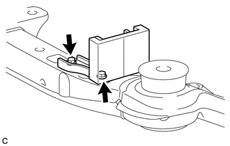
19. REMOVE FRONT SUSPENSION MEMBER DYNAMIC DAMPER (for 2WD)
|
(a) Remove the 2 bolts and front suspension member dynamic damper. |
|
20. REMOVE FRONT SUSPENSION MEMBER BODY MOUNTING FRONT STOPPER
21. REMOVE FRONT SUSPENSION MEMBER BODY MOUNTING REAR STOPPER
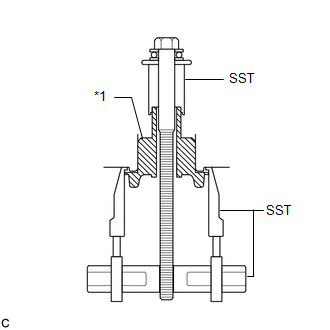
22. REMOVE FRONT SUSPENSION MEMBER BODY MOUNTING FRONT CUSHION
|
(a) Install SST as shown in the illustration. Text in Illustration
SST: 09830-10010 09830-01010 09830-01040 09830-01050 SST: 09950-40011 09951-04020 09952-04010 09955-04011 |
|
|
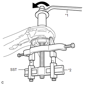
(b) Using SST, remove the front suspension member body mounting front cushion. Text in Illustration
NOTICE:
|
|
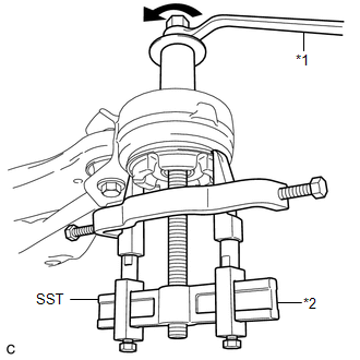
23. REMOVE FRONT SUSPENSION MEMBER BODY MOUNTING REAR CUSHION LH
|
(a) Install SST as shown in the illustration. SST: 09830-10010 09830-01010 09830-01040 09830-01050 SST: 09950-40011 09951-04020 09952-04010 09954-04010 09955-04011 Text in Illustration
|
|
|
(b) Using SST, remove the front suspension member body mounting rear cushion LH. Text in Illustration
SST: 09830-10010 09830-01010 09830-01040 09830-01050 SST: 09950-40011 09951-04020 09952-04010 09954-04010 09955-04011 NOTICE:
|
|
24. REMOVE FRONT SUSPENSION MEMBER BODY MOUNTING REAR CUSHION RH
HINT:
Perform the same procedure as for the LH side.
 Components
COMPONENTS
ILLUSTRATION
ILLUSTRATION
ILLUSTRATION
ILLUSTRATION
...
 Installation
INSTALLATION
PROCEDURE
1. INSTALL FRONT SUSPENSION MEMBER BODY MOUNTING REAR CUSHION LH
(a) Temporarily install a new front suspension member body mounting rear
cushion LH while conf ...
Other materials about Toyota Venza:
Outer Rear View Mirror Glass
Components
COMPONENTS
ILLUSTRATION
Inspection
INSPECTION
PROCEDURE
1. INSPECT OUTER MIRROR RH
(a) Check the outer mirror heater operation.
(1) Measure the resistance according to the value(s) in the table below.
Standard Resistanc ...
Installation
INSTALLATION
CAUTION / NOTICE / HINT
HINT:
Perform "Inspection After Repair" after replacing the camshaft, No. 2 camshaft,
camshaft timing gear assembly or camshaft timing exhaust gear assembly (See page
).
PROCEDURE
1. INSTALL NO. 2 CAMSHAF ...
Installing the spare tire
Remove any dirt or foreign matter from the wheel contact surface.
If foreign matter is on the wheel contact surface, the wheel nuts may loosen
while the vehicle is in motion, and the tire may come off the vehicle.
Install the spare tire and loosely tig ...

0.1231