Toyota Venza: Installation
INSTALLATION
PROCEDURE
1. INSTALL FRONT SUSPENSION MEMBER BODY MOUNTING REAR CUSHION LH
|
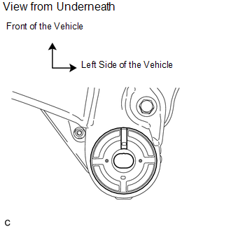
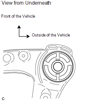
(a) Temporarily install a new front suspension member body mounting rear cushion LH while confirming the installation direction. NOTICE: Position the front suspension member body mounting rear cushion in the correct direction. |
|
|
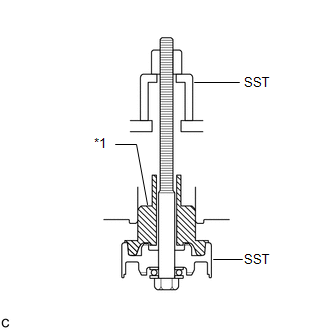
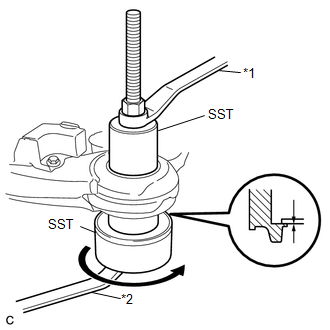
(b) Install SST as shown in the illustration. Text in Illustration
SST: 09830-10010 09830-01010 09830-01020 09830-01030 09830-01060 |
|
|
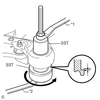
(c) Using SST, install the front suspension member body mounting rear cushion LH as shown in the illustration. Text in Illustration
NOTICE: Make sure that there is no clearance between the front suspension member and front suspension member body mounting rear cushion LH. |
|
2. INSTALL FRONT SUSPENSION MEMBER BODY MOUNTING REAR CUSHION RH
|
(a) Temporarily install a new front suspension member body mounting rear cushion RH while confirming the installation direction. NOTICE: Position the front suspension member body mounting rear cushion in the correct direction. |
|
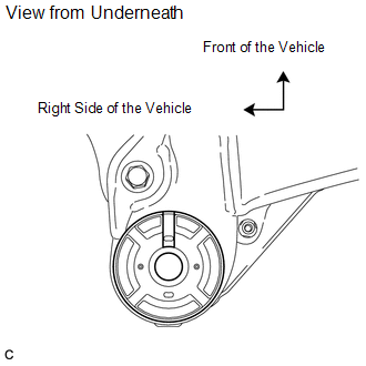
(b) Using SST, install the front suspension member body mounting rear cushion RH.
SST: 09830-10010
09830-01010
09830-01020
09830-01030
09830-01060
HINT:
Perform the same procedure as for the LH side.
3. INSTALL FRONT SUSPENSION MEMBER BODY MOUNTING FRONT CUSHION
|
(a) Temporarily install a new front suspension member body mounting front cushion while confirming the installation direction. NOTICE: Position the front suspension member body mounting front cushion in the correct direction. |
|
|
(b) Using SST, install the front suspension member body mounting front cushion as shown in the illustration. Text in Illustration
SST: 09830-10010 09830-01010 09830-01020 09830-01030 09830-01060 NOTICE: Make sure that there is no clearance between the front suspension member and front suspension member body mounting front cushion. |
|
4. INSTALL FRONT SUSPENSION MEMBER BODY MOUNTING REAR STOPPER
5. INSTALL FRONT SUSPENSION MEMBER BODY MOUNTING FRONT STOPPER
6. INSTALL FRONT SUSPENSION MEMBER DYNAMIC DAMPER (for 2WD)
|
(a) Install the front suspension member dynamic damper with the 2 bolts. Torque: 29 N·m {296 kgf·cm, 21 ft·lbf} |
|
.png)
7. INSTALL FRONT LOWER SUSPENSION ARM LH
.gif)
8. INSTALL FRONT LOWER SUSPENSION ARM RH
HINT:
Perform the same procedure as for the LH side.
9. TEMPORARILY TIGHTEN FRONT ENGINE MOUNTING INSULATOR ASSEMBLY (for 2GR-FE)
10. TEMPORARILY TIGHTEN ENGINE MOUNTING INSULATOR LH (for 2GR-FE)
11. TEMPORARILY TIGHTEN ENGINE MOUNTING INSULATOR RH (for 2GR-FE)
12. TEMPORARILY TIGHTEN REAR ENGINE MOUNTING INSULATOR ASSEMBLY (for 2GR-FE)
13. INSTALL FRONT FRAME ASSEMBLY (for 2GR-FE)
14. FULLY TIGHTEN FRONT ENGINE MOUNTING INSULATOR ASSEMBLY (for 2GR-FE)
15. FULLY TIGHTEN ENGINE MOUNTING INSULATOR LH (for 2GR-FE)
16. FULLY TIGHTEN ENGINE MOUNTING INSULATOR RH (for 2GR-FE)
17. FULLY TIGHTEN REAR ENGINE MOUNTING INSULATOR ASSEMBLY (for 2GR-FE)
18. TEMPORARILY TIGHTEN FRONT ENGINE MOUNTING INSULATOR ASSEMBLY (for 1AR-FE)
19. TEMPORARILY TIGHTEN ENGINE MOUNTING INSULATOR LH (for 1AR-FE)
20. TEMPORARILY TIGHTEN ENGINE MOUNTING INSULATOR RH (for 1AR-FE)
21. TEMPORARILY TIGHTEN REAR ENGINE MOUNTING INSULATOR ASSEMBLY (for 1AR-FE AWD)
22. INSTALL FRONT FRAME ASSEMBLY (for 1AR-FE)
23. INSTALL REAR ENGINE MOUNTING INSULATOR ASSEMBLY (for 1AR-FE AWD)
24. FULLY TIGHTEN FRONT ENGINE MOUNTING INSULATOR ASSEMBLY (for 1AR-FE)
25. FULLY TIGHTEN ENGINE MOUNTING INSULATOR LH (for 1AR-FE)
26. FULLY TIGHTEN ENGINE MOUNTING INSULATOR RH (for 1AR-FE)
27. FULLY TIGHTEN REAR ENGINE MOUNTING INSULATOR ASSEMBLY (for 1AR-FE AWD)
28. INSTALL STEERING LINK ASSEMBLY
29. INSTALL FRONT STABILIZER BAR WITH FRONT STABILIZER LINK ASSEMBLY
30. INSTALL FRONT NO. 1 STABILIZER BRACKET LH
31. INSTALL FRONT NO. 1 STABILIZER BRACKET RH
HINT:
Perform the same procedure as for the LH side.
32. INSTALL ENGINE ASSEMBLY WITH TRANSAXLE (for 2GR-FE)
HINT:
Refer to the procedure from Install Engine Assembly with Transaxle (See page
).
33. INSTALL ENGINE ASSEMBLY WITH TRANSAXLE (for 1AR-FE)
HINT:
Refer to the procedure from Install Engine Assembly with Transaxle (See page
).
 Removal
REMOVAL
PROCEDURE
1. REMOVE ENGINE ASSEMBLY WITH TRANSAXLE (for 2GR-FE)
HINT:
Refer to the procedure up to Remove Engine Assembly with Transaxle (See page
).
2. REMOVE ENGINE ASSEMBLY WITH TRAN ...

Other materials about Toyota Venza:
Installation
INSTALLATION
CAUTION / NOTICE / HINT
HINT:
Use the same procedure for the RH side and LH side.
The procedure listed below is for the LH side.
PROCEDURE
1. INSTALL CURTAIN SHIELD AIRBAG ASSEMBLY
(a) Check that the ignition switch is off. ...
Test Mode Procedure
TEST MODE PROCEDURE
1. WARNING LIGHT AND INDICATOR LIGHT INITIAL CHECK
(a) Release the parking brake.
NOTICE:
Before releasing the parking brake, move the shift lever to P for safety.
HINT:
When the parking brake is applied or the brake fluid level is lo ...
Certification ECU Communication Stop Mode
DESCRIPTION
Detection Item
Symptom
Trouble Area
Certification ECU Communication Stop Mode
"Smart Access/Smart Key/Wireless Tuner" is not displayed on
"CAN Bus Check&q ...

0.1691