Toyota Venza: Components
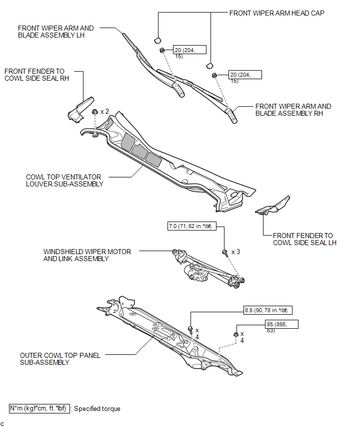
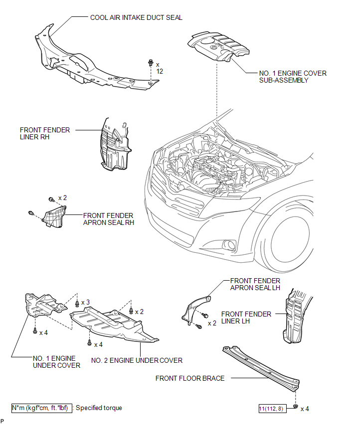
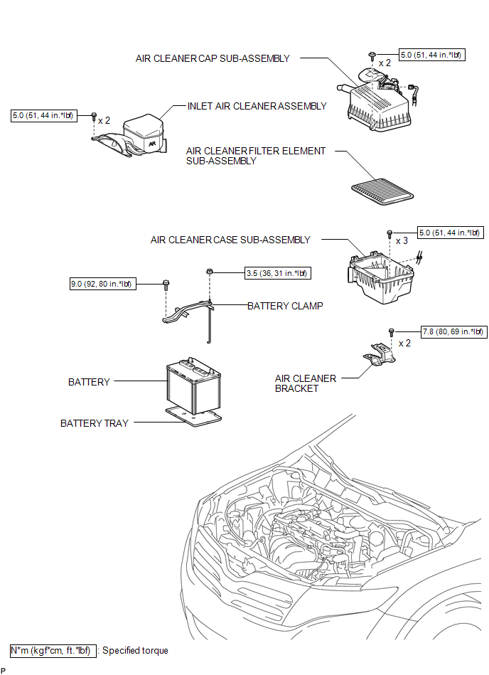
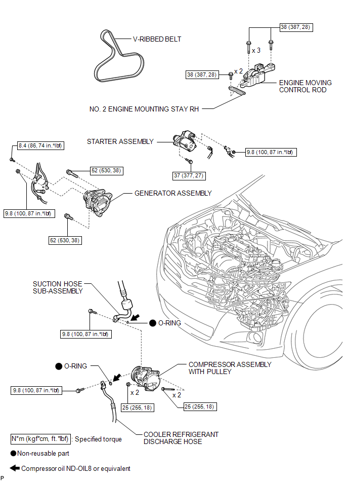
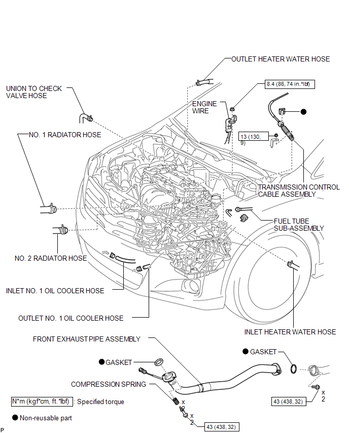
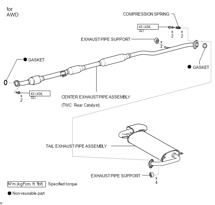
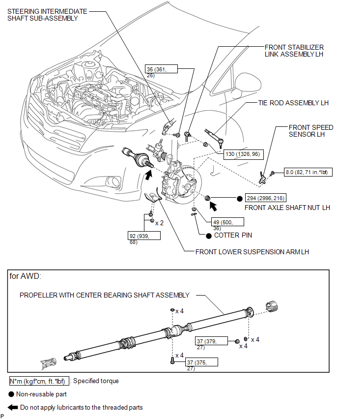
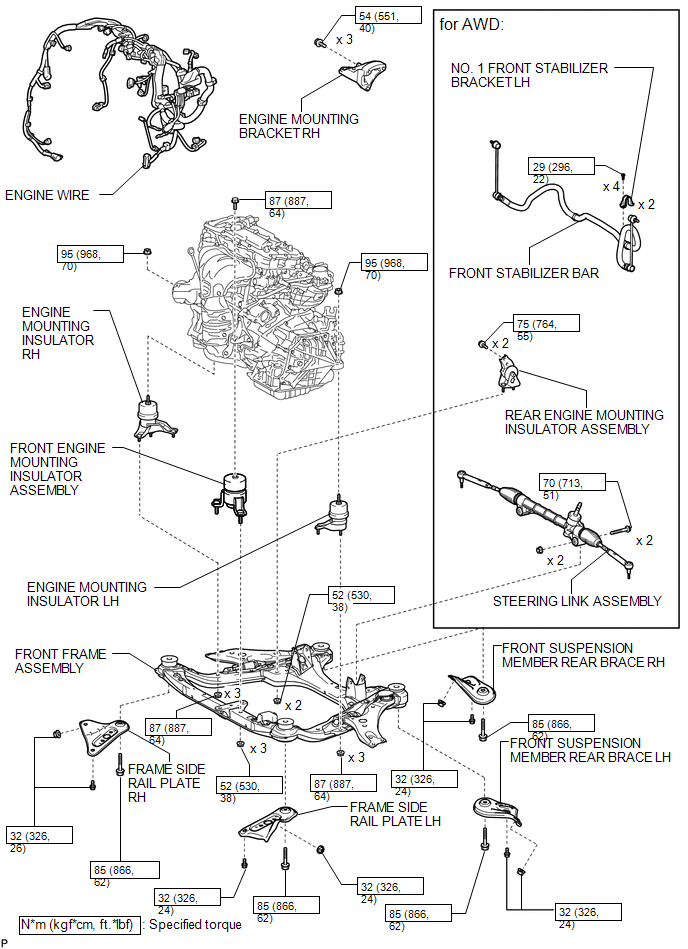
COMPONENTS
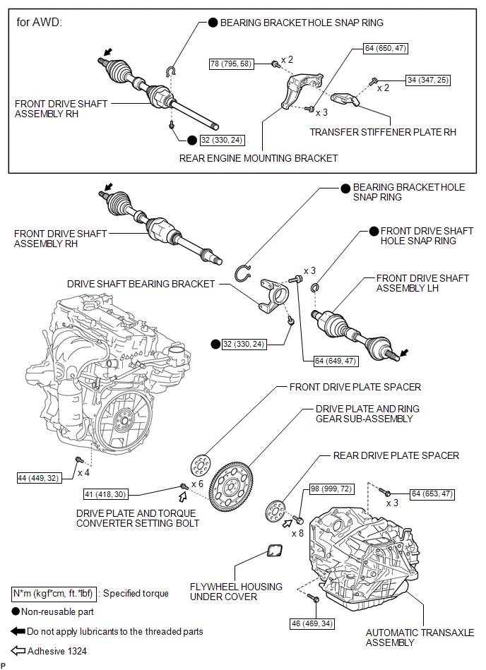
ILLUSTRATION
ILLUSTRATION
ILLUSTRATION
ILLUSTRATION
ILLUSTRATION
ILLUSTRATION
ILLUSTRATION
ILLUSTRATION
ILLUSTRATION
 Engine Assembly
...
 Removal
REMOVAL
PROCEDURE
1. RECOVER REFRIGERANT FROM REFRIGERATION SYSTEM
2. DISCHARGE FUEL SYSTEM PRESSURE
3. PLACE FRONT WHEELS FACING STRAIGHT AHEAD
4. REMOVE FRONT WHEELS
5. DISCONNECT CABLE ...
Other materials about Toyota Venza:
Navigation Voice Circuit
DESCRIPTION
This circuit is used when the voice switch of the steering pad switch assembly
is pushed.
Using this circuit, the navigation receiver assembly sends signals to the stereo
component amplifier assembly.
WIRING DIAGRAM
PROCEDURE
...
Disposal
DISPOSAL
CAUTION / NOTICE / HINT
CAUTION:
Before performing pre-disposal deployment of any SRS component, review and closely
follow all applicable environmental and hazardous material regulations. Pre-disposal
deployment may be considered hazardous mate ...
Problem Symptoms Table
PROBLEM SYMPTOMS TABLE
If there are no DTCs output and the problem still occurs, check the circuits
for each problem symptom in the order given in the following table and proceed to
the relevant troubleshooting page.
NOTICE:
When replacing the brake act ...

0.1317