Toyota Venza: Relay
On-vehicle Inspection
ON-VEHICLE INSPECTION
PROCEDURE
1. INSPECT HORN RELAY (ENGINE ROOM JUNCTION BLOCK ASSEMBLY)
|
(a) Remove the engine room junction block assembly from the engine room
relay block (See page |
|
.gif) ).
).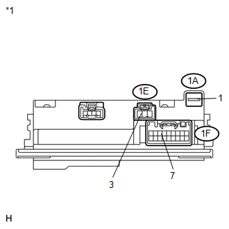
(b) Connect a positive (+) lead from the battery to terminal 1A-1.
(c) Connect a negative (-) lead from the battery to terminal 1F-7.
(d) Measure the voltage according to the value(s) in the table below.
Standard Voltage:
|
Tester Connection |
Condition |
Specified Condition |
|---|---|---|
|
1E-3 - Battery negative |
Always |
11 to 14 V |
|
*1 |
Component without harness connected (Engine Room Junction Block Assembly) |
If the result is not as specified, replace the engine room junction block assembly.
 Horn System
Precaution
PRECAUTION
NOTICE:
When disconnecting the cable from the negative (-) battery terminal, initialize
the following system after the cable is reconnected.
System Name
...
 Lighting (ext)
...
Other materials about Toyota Venza:
Components
COMPONENTS
ILLUSTRATION
ILLUSTRATION
ILLUSTRATION
ILLUSTRATION
ILLUSTRATION
ILLUSTRATION
ILLUSTRATION
ILLUSTRATION
ILLUSTRATION
ILLUSTRATION
ILLUSTRATION
ILLUSTRATION
...
Vsc Off Switch
Components
COMPONENTS
ILLUSTRATION
Removal
REMOVAL
PROCEDURE
1. DISCONNECT CABLE FROM NEGATIVE BATTERY TERMINAL
NOTICE:
When disconnecting the cable, some systems need to be initialized after the cable
is reconnected (See page ).
2. REMOVE FR ...
Removal
REMOVAL
PROCEDURE
1. DRAIN AUTOMATIC TRANSAXLE FLUID
2. REMOVE FRONT FRAME ASSEMBLY
See page
3. SUPPORT ENGINE ASSEMBLY
4. REMOVE BELT
5. REMOVE AUTOMATIC TRANSAXLE OIL PAN SUB-ASSEMBLY
(a) Remove the 18 bolts and automatic transa ...

0.1607