Toyota Venza: Electrical Key Oscillator(for Center Floor)
Components
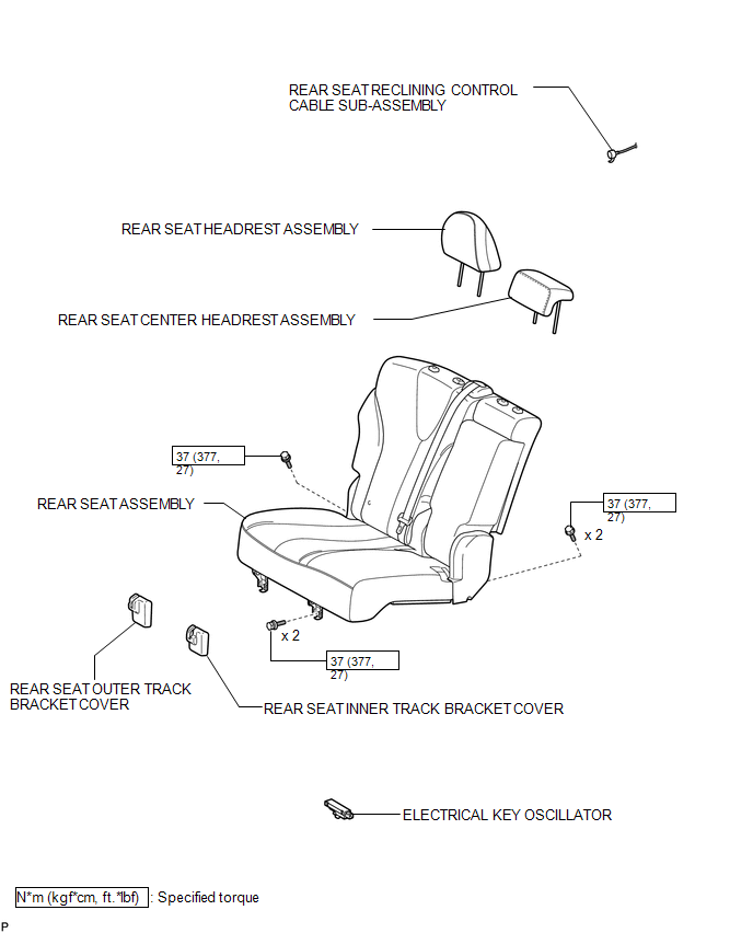
COMPONENTS
ILLUSTRATION
Installation
INSTALLATION
PROCEDURE
1. INSTALL ELECTRICAL KEY OSCILLATOR
|
(a) Engage the clamp and install the electrical key oscillator. NOTICE: Be careful when installing the electrical key oscillator. If the oscillator is dropped, replace it with a new one. |
|
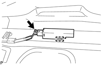
(b) Connect the connector.
2. INSTALL REAR SEAT ASSEMBLY
.gif)
3. CONNECT REAR SEAT RECLINING CONTROL CABLE SUB-ASSEMBLY
4. INSTALL REAR SEAT OUTER TRACK BRACKET COVER
5. INSTALL REAR SEAT INNER TRACK BRACKET COVER
6. INSTALL REAR SEAT CENTER HEADREST ASSEMBLY
7. INSTALL REAR SEAT HEADREST ASSEMBLY
Removal
REMOVAL
PROCEDURE
1. REMOVE REAR SEAT HEADREST ASSEMBLY
.gif)
2. REMOVE REAR SEAT CENTER HEADREST ASSEMBLY
3. REMOVE REAR SEAT INNER TRACK BRACKET COVER
4. REMOVE REAR SEAT OUTER TRACK BRACKET COVER
5. DISCONNECT REAR SEAT RECLINING CONTROL CABLE SUB-ASSEMBLY
6. REMOVE REAR SEAT ASSEMBLY
7. REMOVE ELECTRICAL KEY OSCILLATOR
|
(a) Disconnect the connector. |
|
.png)
(b) Disengage the clamp and the electrical key oscillator.
NOTICE:
Be careful when removing the electrical key oscillator. If the oscillator is dropped, replace it with a new one.
 Certification Ecu
Components
COMPONENTS
ILLUSTRATION
Removal
REMOVAL
PROCEDURE
1. DISCONNECT CABLE FROM NEGATIVE BATTERY TERMINAL
CAUTION:
Wait at least 90 seconds after disconnecting the cable from the n ...
 Electrical Key Oscillator(for Front Floor)
Components
COMPONENTS
ILLUSTRATION
Installation
INSTALLATION
PROCEDURE
1. INSTALL ELECTRICAL KEY OSCILLATOR
(a) Engage the clamp and install the electrical key oscillator.
N ...
Other materials about Toyota Venza:
Cleaning and protecting the vehicle exterior
Perform the following to protect the vehicle and maintain it in prime condition.
• Working from top to bottom, liberally apply water to the vehicle body, wheel
wells and underside of the vehicle to remove any dirt and dust.
Wash the vehicle body using a ...
Data List / Active Test
DATA LIST / ACTIVE TEST
HINT:
Using the Techstream to read the Data List allows the values or states of switches,
sensors, actuators and other items to be read without removing any parts. This non-intrusive
inspection can be very useful because intermitt ...
Reassembly
REASSEMBLY
CAUTION / NOTICE / HINT
NOTICE:
When using a vise, do not overtighten it.
PROCEDURE
1. INSTALL STEERING LOCK ACTUATOR ASSEMBLY (w/ Smart Key System)
(a) Secure the steering column assembly in a vise.
(b) Temporarily install the ste ...

0.1456