Toyota Venza: Reassembly
REASSEMBLY
PROCEDURE
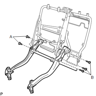
1. INSTALL REAR SEAT LEG ASSEMBLY RH
|
(a) Using a T55 "TORX" socket wrench, install the rear seat leg assembly RH with the 5 "TORX" bolts. Torque: A : 42 N·m {428 kgf·cm, 31 ft·lbf} B : 55 N·m {560 kgf·cm, 41 ft·lbf} |
|
2. INSTALL REAR CENTER SEATBACK HINGE
|
(a) Using a T45 "TORX" socket wrench, install the bush and "TORX" bolt. Torque: 21 N·m {214 kgf·cm, 16 ft·lbf} |
|
.png)
(b) Install the rear center seatback hinge with the bolt.
Torque:
21 N·m {214 kgf·cm, 16 ft·lbf}
3. INSTALL REAR SEAT LEG SIDE COVER LH
|
(a) Install the rear seat leg side cover LH with the 2 screws. |
|
.png)
4. INSTALL REAR SEAT LEG SIDE COVER RH
|
(a) Install the rear seat leg side cover RH with the 2 screws. |
|
.png)
5. INSTALL REAR SEAT CUSHION FRAME SUB-ASSEMBLY RH
|
(a) Install the 2 bolts. Torque: 18 N·m {184 kgf·cm, 13 ft·lbf} |
|
.png)
(b) Using a T45 "TORX" socket wrench, install the rear seat cushion frame sub-assembly RH with the 3 "TORX" bolts and 3 bushes.
Torque:
21 N·m {214 kgf·cm, 16 ft·lbf}
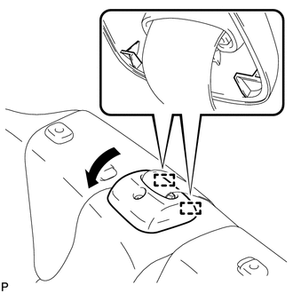
6. INSTALL RECLINING ADJUSTER INSIDE COVER LH
|
(a) Engage the claw and 2 guides. |
|
.png)
(b) Install the reclining adjuster inside cover LH with the 2 screws.
7. INSTALL RECLINING ADJUSTER INSIDE COVER RH
|
(a) Engage the claw and 2 guides. |
|
.png)
(b) Install the reclining adjuster inside cover RH with the 2 screws.
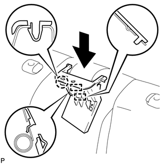
8. INSTALL REAR SEAT RECLINING CONTROL CABLE SUB-ASSEMBLY
|
(a) Engage the claw. |
|
.png)
(b) Engage 2 new clamps.
(c) Engage the 4 cable clamps to install the rear seat reclining control cable sub-assembly.
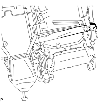
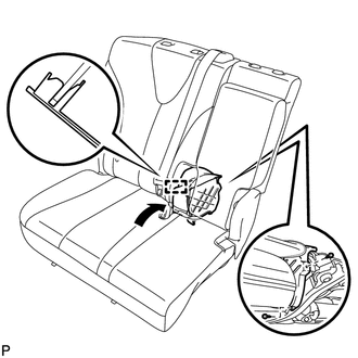
9. INSTALL REAR CENTER SEAT OUTER BELT ASSEMBLY
.gif)
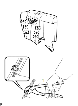
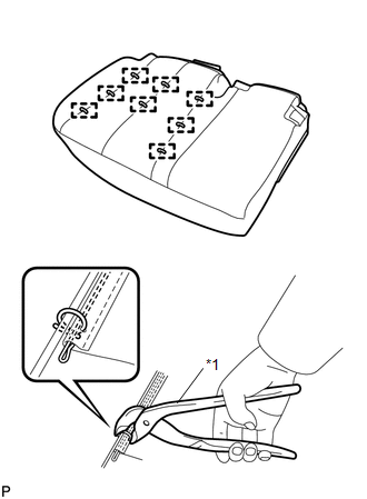
10. INSTALL SEPARATE TYPE REAR SEATBACK COVER
|
(a) Using hog ring pliers, install the c with 10 new hog rings. Text in Illustration
NOTICE:
|
|
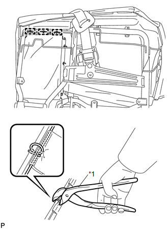
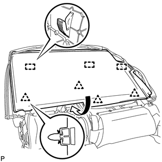
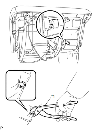
11. INSTALL REAR SEATBACK COVER WITH PAD
|
(a) Using hog ring pliers, install 3 new hog rings. Text in Illustration
NOTICE:
|
|
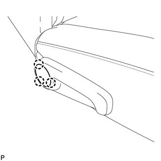
|
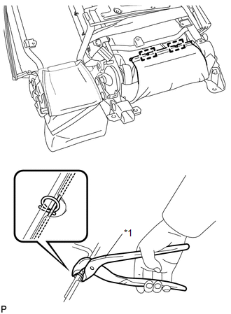
(b) Using hog ring pliers, install 2 new hog rings. Text in Illustration
NOTICE:
|
|
|
(c) Engage the hook to install the rear seat cushion cover with pad. |
|
12. INSTALL REAR SEAT CENTER HEADREST SUPPORT RH
|
(a) Engage the 2 claws to install the rear seat center headrest support RH. |
|
.png)
13. INSTALL REAR SEAT CENTER HEADREST SUPPORT LH
|
(a) Engage the 2 claws to install the rear seat center headrest support LH. |
|
.png)
14. INSTALL REAR SEAT HEADREST SUPPORT RH
|
(a) Engage the 2 claws to install the rear seat headrest support RH. |
|
.png)
15. INSTALL REAR SEAT HEADREST SUPPORT LH
|
(a) Engage the 2 claws to install the rear seat headrest support LH. |
|
.png)
16. INSTALL REAR SEAT SHOULDER BELT COVER
|
(a) Engage the 2 guides and claw, and install the rear seat shoulder belt cover as shown in the illustration. |
|
|
(b) Engage the 2 guides as shown in the illustration. |
|
|
(c) Install the rear seatback upper lock bezel with the screw. |
|
.png)
17. INSTALL CUP HOLDER
|
(a) Install the cup holder with the 2 screws. |
|
.png)
18. INSTALL REAR SEATBACK HINGE LH
|
(a) Install the rear seatback hinge LH with the 2 bolts and 2 bushes. Torque: 6.0 N·m {61 kgf·cm, 53 in·lbf} |
|
.png)
19. INSTALL REAR SEAT CENTER ARMREST ASSEMBLY
|
(a) Install the 3 nuts. Torque: 6.0 N·m {61 kgf·cm, 53 in·lbf} |
|
.png)
|
(b) Engage the hook and install the rear seat center armrest assembly. |
|
.png)
20. INSTALL CUP HOLDER HOLE COVER
|
(a) Install the 2 new cup holder hole covers. |
|
.png)
21. INSTALL REAR SEATBACK BOARD RH
|
(a) Engage the 3 guides and 4 clips as shown in the illustration. |
|
|
(b) Engage the 20 claws and install the rear seatback board RH. |
|
.png)
22. CONNECT REAR CENTER SEAT OUTER BELT ASSEMBLY
23. INSTALL REAR SEAT INNER BELT ASSEMBLY RH
24. INSTALL SEPARATE TYPE REAR SEAT CUSHION COVER
|
(a) Using hog ring pliers, install the separate type rear seat cushion cover with 8 new hog rings. Text in Illustration
NOTICE:
|
|
25. INSTALL REAR SEAT CUSHION COVER WITH PAD
|
(a) Engage each hook as shown in the illustration. |
|
.png)
|
(b) Engage the 4 hooks. |
|
.png)
|
(c) Using hog ring pliers, install the rear seat cushion cover with pad with a new hog ring. Text in Illustration
NOTICE:
|
|
|
(d) Engage the hook to install the rear seat cushion with pad. |
|
.png)
26. INSTALL REAR SEAT RECLINING COVER RH
|
(a) Engage the 2 guides. |
|
.png)
(b) Install the rear seat reclining cover RH with the 2 screws.
27. INSTALL CENTER SEAT HINGE COVER RH
|
(a) Disengage the guide as shown in the illustration. |
|
(b) Install the center seat hinge cover RH with the 2 screws.
28. INSTALL REAR SEAT INNER RECLINING COVER RH
|
(a) Engage the guide. |
|
.png)
(b) Install the rear seat inner reclining cover RH with the 2 screws.
29. INSTALL REAR SEAT RECLINING RELEASE LEVER RH
|
(a) Install the rear seat reclining release lever RH with the 3 screws. |
|
.png)
30. INSTALL SEAT ADJUSTER COVER CAP RH
|
(a) Engage the 3 claws to install the seat adjuster cover cap RH. |
|
 Disassembly
DISASSEMBLY
PROCEDURE
1. REMOVE SEAT ADJUSTER COVER CAP RH
(a) Using a screwdriver wrapped with protective tape, disengage the 3
claws and remove the seat adjuster cover cap RH.
T ...
 Installation
INSTALLATION
PROCEDURE
1. INSTALL REAR SEAT ASSEMBLY RH
(a) Place the rear seat assembly RH in the cabin.
NOTICE:
Be careful not to damage the vehicle body.
(b) Temporarily install th ...
Other materials about Toyota Venza:
Installation
INSTALLATION
PROCEDURE
1. INSTALL PARK/NEUTRAL POSITION SWITCH ASSEMBLY
(a) Move the shift lever to N.
(b) Align the protrusions of the park/neutral position switch.
Text in Illustration
*1
Protrusion
...
Rear Door RH ECU Communication Stop (B2323)
DESCRIPTION
This DTC is stored when LIN communication between the power window regulator
motor assembly (for rear RH side) and main body ECU (driver side junction block
assembly) stops for more than 10 seconds.
DTC No.
DTC Detection ...
Setting up the displays
Press the “SETUP” button while the
vehicle is stopped.
The “Custom Settings” screen is displayed on the multi-information display.
If left idle for approximately 10 seconds, the display will revert to the previous
screen.
Select “Display / ...

0.13