Toyota Venza: Reassembly
REASSEMBLY
PROCEDURE
1. INSTALL MAGNETIC CLUTCH ASSEMBLY
|
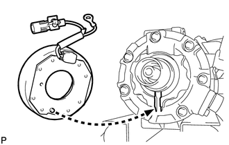
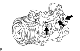
(a) Install the magnetic clutch stator while aligning the protrusion on the stator with the notch on the air compressor assembly as shown in the illustration. |
|
|
(b) Engage the clamp. |
|
.png)
(c) Install the bracket with the screw.
(d) Connect the connector.
|
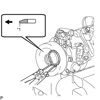
(e) Using a snap ring expander, install a new snap ring with the chamfered side facing up. Text in Illustration
NOTICE: Take care not to damage the seal cover of the bearing when installing the snap ring. |
|
|
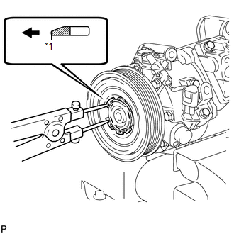
(f) Using a snap ring expander, install the magnetic clutch rotor and a new snap ring with the chamfered side facing up. Text in Illustration
NOTICE:
|
|
(g) Install the magnetic clutch washers and magnetic clutch hub.
NOTICE:
Do not change the combination of the magnetic clutch washers used before disassembly.
|
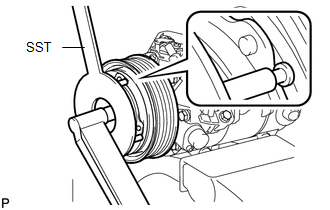
(h) Using SST, hold the magnetic clutch hub and install the bolt. SST: 09985-00270 Torque: 18 N·m {184 kgf·cm, 13 ft·lbf} NOTICE: Make sure that there is no foreign matter or oil on the compressor shaft, bolt and clutch hub. |
|
2. INSPECT MAGNETIC CLUTCH CLEARANCE
|
(a) Set the dial indicator to the magnetic clutch hub. |
|
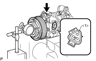
(b) Connect a positive (+) lead from the battery to terminal 1 of the magnetic clutch connector, and a negative (-) lead to the ground wire. Turn the magnetic clutch on and off and measure the clearance.
Standard clearance:
0.26 to 0.60 mm (0.0103 to 0.0236 in.)
If the measured value is not within the standard range, remove the magnetic clutch hub and adjust it with magnetic clutch washers.
NOTICE:
Adjustment should be performed with 3 or less magnetic clutch washers.
(c) Remove the compressor and magnetic clutch from the vise.
3. ADJUST COMPRESSOR OIL LEVEL
|
(a) When replacing the compressor and magnetic clutch with a new one, gradually discharge the refrigerant from the service valve, and drain the following amount of oil from the new compressor and magnetic clutch before installation. Standard: (Oil capacity inside the new compressor and magnetic clutch: 130 + 15 cc (4.4 + 0.51 fl.oz.) ) - (Remaining oil amount in the removed compressor and magnetic clutch) = (Oil amount to be removed from the new compressor when replacing) NOTICE:
|
|
 Installation
INSTALLATION
PROCEDURE
1. TEMPORARILY TIGHTEN COMPRESSOR AND MAGNETIC CLUTCH
(a) Temporarily install the compressor and magnetic clutch and bracket
with the 4 bolts.
...
 Condenser
...
Other materials about Toyota Venza:
Operation Check
OPERATION CHECK
1. CHECK POWER SEAT FUNCTION
(a) Check the basic functions.
(1) Operate the power seat switches and check to make sure each seat function
work:
Sliding
Front vertical (Driver side only)
Lumbar support
Lifter (Driver s ...
Installation
INSTALLATION
PROCEDURE
1. INSTALL NO. 3 ANTENNA CORD SUB-ASSEMBLY
(a) Pass the washer hose through the No. 3 antenna cord sub-assembly.
(b) Pass the No. 3 antenna cord sub-assembly with washer hose through
the vehicle body as shown in the il ...
Fail-safe Chart
FAIL-SAFE CHART
If any of the following DTCs are stored, the ECM enters fail-safe mode to allow
the vehicle to be driven temporarily or stops fuel injection.
DTC Code
Component
Fail-Safe Operation
Fail-Safe Deact ...

0.1441