Toyota Venza: Removal
REMOVAL
PROCEDURE
1. PRECAUTION
NOTICE:
Be sure to read Precaution thoroughly before servicing (See page
.gif) ).
).
2. REMOVE SHIFT LEVER ASSEMBLY
(See page )
3. DISCONNECT INSTRUMENT PANEL WIRE ASSEMBLY
(a) Check that the ignition switch is off.
(b) Check that the cable is disconnected from the negative (-) battery terminal.
CAUTION:
Wait at least 90 seconds after disconnecting the cable from the negative (-) battery terminal to disable the SRS system.
|
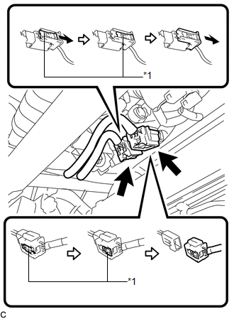
(c) Slide the 2 sliders to release the 2 locks, and then disconnect the 2 connectors. Text in Illustration
NOTICE: When disconnecting the airbag connector, take care not to damage the airbag wire harness. |
|
4. REMOVE INSTRUMENT PANEL SAFETY PAD ASSEMBLY
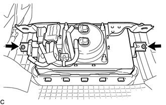
5. REMOVE FRONT PASSENGER AIRBAG ASSEMBLY
CAUTION:
When storing the front passenger airbag assembly, keep the airbag deployment side facing upward.
|
(a) Remove the 2 screws. |
|
|
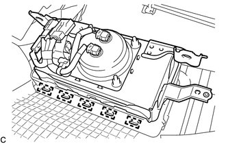
(b) Lean the instrument panel to disengage the 5 hooks. |
|
|
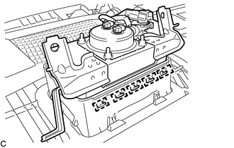
(c) Disengage the 5 hooks to remove the front passenger airbag assembly from the instrument panel safety pad assembly. |
|
6. REMOVE INSTRUMENT PANEL WIRE ASSEMBLY
|
(a) Disengage the 2 clamps. Text in Illustration
|
|
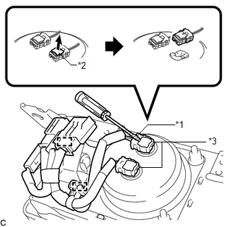
(b) Using a screwdriver with its tip wrapped with protective tape, release the 2 airbag connector locks.
(c) Disconnect the 2 airbag connectors.
NOTICE:
When disconnecting any airbag connector, take care not to damage the airbag wire harness.
|
(d) Using a screwdriver with its tip wrapped with protective tape, release the vent hole connector lock. Text in Illustration
|
|
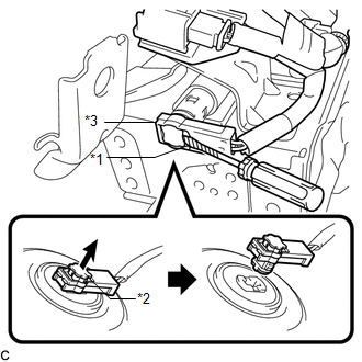
(e) Disconnect the vent hole connector to remove the instrument panel wire from the front passenger airbag assembly.
NOTICE:
When disconnecting any airbag connector, take care not to damage the airbag wire harness.
 On-vehicle Inspection
ON-VEHICLE INSPECTION
CAUTION / NOTICE / HINT
CAUTION:
Be sure to correctly follow the removal and installation procedures for the front
passenger airbag assembly.
PROCEDURE
1. INSPECT FRONT PA ...
 Installation
INSTALLATION
PROCEDURE
1. INSTALL INSTRUMENT PANEL WIRE ASSEMBLY
(a) Connect the vent hole connector of the instrument panel wire to the
front passenger airbag assembly.
Text in I ...
Other materials about Toyota Venza:
Vehicle Speed Sensor "A" (P0500)
DESCRIPTION
The speed sensor detects the wheel speed and sends the appropriate signals to
the skid control ECU.
The skid control ECU converts these wheel speed signals into a 4-pulse signal
and outputs it to the ECM via the combination meter. The ECM det ...
Removal
REMOVAL
PROCEDURE
1. REMOVE NO. 1 ENGINE UNDER COVER
2. REMOVE NO. 2 ENGINE UNDER COVER
3. REMOVE WINDSHIELD WIPER MOTOR AND LINK
(a) Remove the windshield wiper motor and link (See page
).
4. REMOVE OUTER COWL TOP PANEL SUB-ASSEMBLY
5. DRAIN ENGIN ...
Power Back Door cannot be Operated Using Any Switch
DESCRIPTION
When the power back door cannot be operated using any switch, one of the following
may be the cause: 1) initialization of the power back door ECU (power back door
motor unit), 2) power back door touch sensor circuit, 3) power back door main sw ...

0.1398