Toyota Venza: Reassembly
REASSEMBLY
PROCEDURE
1. INSTALL FRONT BLOWER MOTOR SUB-ASSEMBLY
|
(a) Install the front blower motor sub-assembly with the 3 screws. |
|
.png)
2. INSTALL AIR INLET SERVO MOTOR SUB-ASSEMBLY
|
(a) Install the air inlet servo motor sub-assembly with the 3 screws. |
|
.png)
|
(b) Engage the 6 claws. |
|
.png)
(c) install the blower case with the screw.
3. INSTALL AIR CONDITIONING AMPLIFIER ASSEMBLY
|
(a) Install the air conditioning amplifier assembly with the 2 screws. |
|
.png)
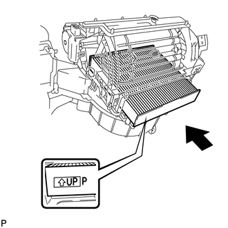
4. INSTALL CLEAN AIR FILTER
|
(a) Install the clean air filter as shown in the illustration. |
|
5. INSTALL AIR FILTER COVER PLATE
|
(a) Engage the 2 claws to install the air filter cover plate. |
|
.png)
6. INSTALL NO. 1 AIR DUCT SUB-ASSEMBLY
|
(a) Engage the 4 claws to install the No. 1 air duct sub-assembly. |
|
.png)
 Disassembly
DISASSEMBLY
PROCEDURE
1. REMOVE NO. 1 AIR DUCT SUB-ASSEMBLY
(a) Disengage the 4 claws and remove the No. 1 air duct sub-assembly.
2. REMOV ...
 Installation
INSTALLATION
PROCEDURE
1. INSTALL NO. 1 COOLER THERMISTOR
2. INSTALL COOLER EVAPORATOR SUB-ASSEMBLY
3. INSTALL BLOWER ASSEMBLY WITH COOLER EVAPORATOR SUB-ASSEMBLY
(a) Engage the 5 claws.
( ...
Other materials about Toyota Venza:
Terminals Of Ecu
TERMINALS OF ECU
1. POWER WINDOW REGULATOR MASTER SWITCH ASSEMBLY
(a) Disconnect the I6 power window regulator master switch assembly connector.
(b) Measure the voltage and resistance according to the value(s) in the table
below.
HINT:
Measure the val ...
Diagnostic Trouble Code Chart
DIAGNOSTIC TROUBLE CODE CHART
Power Window Control System
DTC Code
Detection Item
Trouble Area
See page
B2311
Power Window Motor Malfunction
1. Battery disconnected when ignit ...
On-vehicle Inspection
ON-VEHICLE INSPECTION
CAUTION / NOTICE / HINT
CAUTION:
Be sure to follow the correct removal and installation procedures of the front
airbag sensor.
PROCEDURE
1. INSPECT FRONT AIRBAG SENSOR (VEHICLE NOT INVOLVED IN COLLISION)
(a) Perform a diagnostic s ...

0.1299