Toyota Venza: Adjustment
ADJUSTMENT
CAUTION / NOTICE / HINT
HINT:
It is possible that a bulb is incorrectly installed, affecting headlight aim. Bulb installation should be considered prior to performing the adjustment procedure.
PROCEDURE
1. PREPARE VEHICLE FOR HEADLIGHT AIM ADJUSTMENT
(a) Prepare the vehicle:
- Ensure there is no damage or deformation to the body around the headlights.
- Fill the fuel tank.
- Make sure that the oil is filled to the specified level.
- Make sure that the coolant is filled to the specified level.
- Inflate the tires to the appropriate pressure.
- Unload the trunk and vehicle, ensuring that the spare tire, tools and jack are in their original positions.
- Sit a person of average weight (68 kg, 150 lb) in the driver's seat.
2. PREPARE FOR HEADLIGHT AIMING (Using a headlight aim test machine)
(a) Adjust the headlight aim in accordance with the headlight aim test machine instructions.
3. PREPARE FOR HEADLIGHT AIMING (Using a screen)
|
(a) Prepare the vehicle:
|
|
(b) Prepare a piece of thick white paper (approximately 2 m (6.6 ft.) (height) x 4 m (13.1 ft.) (width)) to use as a screen.
(c) Draw a vertical line down the center of the screen (V line).
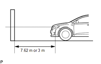
(d) Set the screen as shown in the illustration.
HINT:
- Stand the screen perpendicular to the ground.
- Align the V line on the screen with the center of the vehicle.
|
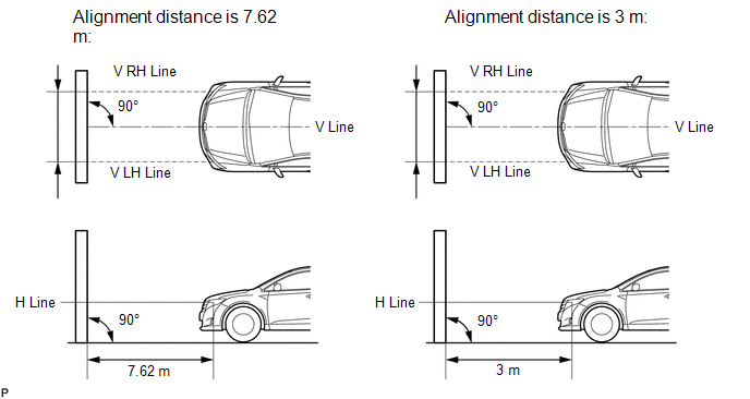
(e) Draw base lines (H, V LH, and V RH lines) on the screen as shown in the illustration. HINT:
(1) H Line (Headlight height): Draw a horizontal line across the screen so that it passes through the center marks. The H line should be at the same height as the headlight bulb center marks of the low beam headlights. (2) V LH Line, V RH Line (Center mark position of left-hand (LH) and right-hand (RH) headlights): Draw 2 vertical lines so that they intersect the H line at each center mark (aligned with the center of the low beam headlight bulbs). |
|
.png)
4. INSPECT HEADLIGHT AIMING
(a) Cover the headlight or disconnect the connector of the headlight/headlight ECU on the opposite side to prevent light from the headlight that is not being inspected from affecting the headlight aiming inspection.
CAUTION:
Do not disconnect the HID high voltage connector for the bulb when performing this aiming inspection. (for HID headlight)
NOTICE:
Do not keep the headlight covered for more than 3 minutes. The headlight lens is made of synthetic resin, which may melt or be damaged due to excessive heat.
HINT:
When checking the aim of the high beam, cover the low beam or disconnect the connector.
(b) Start the engine.
(c) Turn the headlights and check if the aiming of each beam.
HINT:
Preferred position for the low beam: Matches preferred cutoff line shown in the illustration
Preferred position for the high beam: Matches center of intensity shown in the illustration
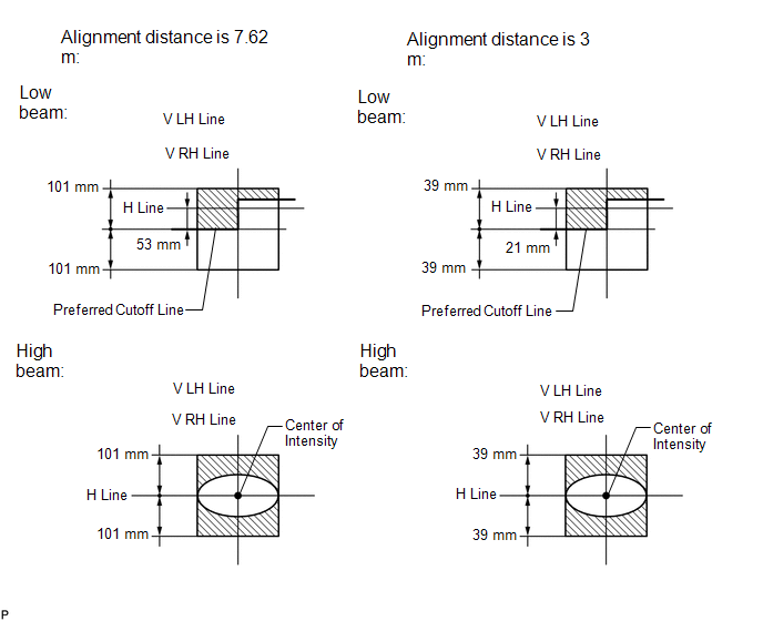
(1) for Halogen Headlight:
HINT:
- Since the low beam light and the high beam light are a unit, if the aim on the low beam is correct, the high beam should also be correct. However, check both beams just to make sure.
- If the alignment distance is 7.62 m (25 ft.):
The left half of the low beam cutoff line should be within 101 mm (3.97 in.) above or below a line drawn 53 mm (2.09 in.) below the H line (SAEJ599).
- If the alignment distance is 3 m (9.84 ft.):
The left half of the low beam cutoff line should be within 39 mm (1.56 in.) above or below a line drawn 21 mm (0.825 in.) below the H line (SAEJ599).
- If the alignment distance is 7.62 m (25 ft.):
The high beam center of intensity should be within 101 mm (3.97 in.) above or below the H line (SAEJ599).
- If the alignment distance is 3 m (9.84 ft.):
The high beam center of intensity should be within 39 mm (1.56 in.) above or below the H line (SAEJ599).
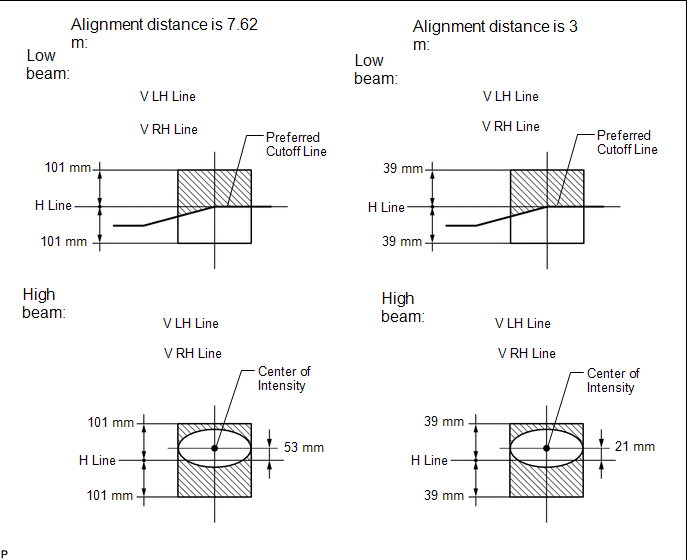
- If the alignment distance is 7.62 m (25 ft.):
The left half of the low beam cutoff line should be 53 mm (2.09 in.) below the H line (preferred cutoff line target).
- If the alignment distance is 3 m (9.84 ft.):
The left half of the low beam cutoff line should be 21 mm (0.825 in.) below the H line (preferred cutoff line target).
- If the alignment distance is 7.62 m (25 ft.):
The high beam center of intensity should be on the H line (preferred center of intensity).
- If the alignment distance is 3 m (9.84 ft.):
The high beam center of intensity should be on the H line (preferred center of intensity).
(2) for HID Headlight:
HINT:
- Since the low beam light and the high beam light are a unit, if the aim on the low beam is correct, the high beam should also be correct. However, check both beams just to make sure.
- If the alignment distance is 7.62 m (25 ft.):
The right half of the low beam cutoff line should be within 101 mm (3.97 in.) above or below the H line (SAE J599).
- If the alignment distance is 3 m (9.84 ft.):
The right half of the low beam cutoff line should be within 39 mm (1.56 in.) above or below the H line (SAE J599).
- If the alignment distance is 7.62 m (25 ft.):
The high beam center of intensity should be within 101 mm (3.97 in.) above or below the H line (SAE J599).
- If the alignment distance is 3 m (9.84 ft.):
The high beam center of intensity should be within 39 mm (1.56 in.) above or below the H line (SAE J599).
- If the alignment distance is 7.62 m (25 ft.):
The right half of the low beam cutoff line should be on the H line (preferred cutoff line target).
- If the alignment distance is 3 m (9.84 ft.):
The right half of the low beam cutoff line should be on the H line (preferred cutoff line target).
- If the alignment distance is 7.62 m (25 ft.):
The high beam center of intensity should be 53 mm (2.09 in.) above the H line (preferred center of intensity).
- If the alignment distance is 3 m (9.84 ft.):
The high beam center of intensity should be 21 mm (0.825 in.) above the H line (preferred center of intensity).
5. ADJUST HEADLIGHT AIMING
(a) Remove any covers necessary to access the headlight adjusters.
(b) Adjust the aim vertically:
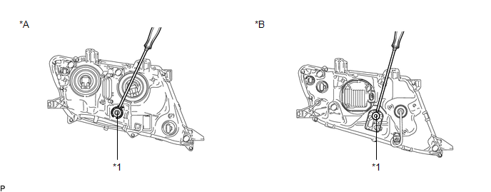 Text in Illustration
|
*A |
for Halogen Headlight |
*B |
for HID Headlight |
|
*1 |
Aiming Screw |
- |
- |
Adjust the aim of each headlight to the specified range by turning each aiming screw with a screwdriver.
NOTICE:
The final turn of the aiming screw should be made in the clockwise direction. If the screw is tightened excessively, loosen it and then retighten it, so that the final turn of the screw is in the clockwise direction.
HINT:
- The low beam light and the high beam light are a unit. Adjusting the aim on the low beam to the correct position should also result in the high beam adjustment being correct.
- If it is not possible to correctly adjust headlight aim, check bulb, headlight unit and headlight unit reflector installation.
- The headlight aim moves down when turning the aiming screw clockwise, and moves up when turning the aiming screw counterclockwise.
- Confirm the direction of rotation of the aiming screw by observing it while it is being adjusted. Due to the position of the screwdriver, the direction of rotation of the adjusting screw can be different than the direction of rotation of the screwdriver being used to adjust it.
(c) Install any covers that were removed to access the headlight adjusters.
 Removal
REMOVAL
CAUTION / NOTICE / HINT
HINT:
Use the same procedure for the RH and LH sides.
The procedure described below is for the LH side.
PROCEDURE
1. PRECAUTION (for HID Headligh ...
 Reassembly
REASSEMBLY
PROCEDURE
1. INSTALL FRONT SIDE MARKER LIGHT BULB
(a) Install the front side marker light bulb to the front side marker light socket.
(b) Turn the front side marker light soc ...
Other materials about Toyota Venza:
Disassembly
DISASSEMBLY
CAUTION / NOTICE / HINT
NOTICE:
When using a vise, do not overtighten it.
PROCEDURE
1. REMOVE STEERING LOCK ACTUATOR ASSEMBLY (w/ Smart Key System)
(a) Secure the steering column assembly in a vise.
(b) Using a center punch, mark the center ...
PIG Power Supply Voltage Malfunction (C1552)
DESCRIPTION
When a problem occurs in the power steering system, the power source relay circuit
is shut off to stop the power assist.
DTC No.
DTC Detection Condition
Trouble Area
C1552
PIG power s ...
Transfer Case Rear Oil Seal
Components
COMPONENTS
ILLUSTRATION
ILLUSTRATION
Replacement
REPLACEMENT
PROCEDURE
1. REMOVE TAIL EXHAUST PIPE ASSEMBLY
2. REMOVE CENTER EXHAUST PIPE ASSEMBLY
3. REMOVE PROPELLER WITH CENTER BEARING SHAFT ASSEMBLY
4. REMOVE TRANSFER C ...

0.1304