
Toyota Venza: Rear differential (AWD models)
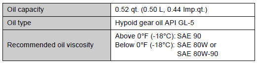

 Automatic transaxle
NOTICE
- Automatic transaxle fluid type
Using transaxle fluid other than “Toyota Genuine ATF WS” may cause deterioration
in shift quality, locking up of your transaxle accompanied by v ...
Other materials about Toyota Venza:
Do-it-yourself service precautions
If you perform maintenance yourself, be sure to follow the correct procedure
given in these sections.
CAUTION
The engine compartment contains many mechanisms and fluids that may move suddenly,
become hot, or become electrically energized. To avoid de ...
Disassembly
DISASSEMBLY
PROCEDURE
1. REMOVE BREATHER PLUG HOSE
(a) Using a screwdriver, remove the No. 2 breather plug (ATM) from the
transaxle case sub-assembly.
(b) Using a screwdriver, remove ...
Afs Ecu
Components
COMPONENTS
ILLUSTRATION
Installation
INSTALLATION
PROCEDURE
1. INSTALL AFS ECU
(a) Engage the guide.
(b) Install the AFS ECU with the bolt.
(c) Connect the connector.
2. INSTA ...

0.1271