Toyota Venza: Rear Brake Flexible Hose
Components
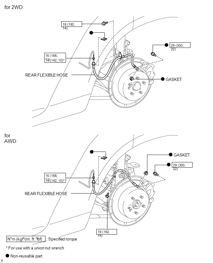
COMPONENTS
ILLUSTRATION
Removal
REMOVAL
CAUTION / NOTICE / HINT
NOTICE:
If both the left and right side hoses are removed at the same time, be sure to place identification marks indicating the position on each side.
HINT:
- Use the same procedure for the LH side and RH side.
- The following procedure listed is for the LH side.
PROCEDURE
1. REMOVE REAR WHEEL
2. DRAIN BRAKE FLUID
NOTICE:
If brake fluid leaks onto any painted surface, immediately wash it off.
3. REMOVE REAR FLEXIBLE HOSE
|
(a) Remove the union bolt and gasket, and separate the rear flexible hose. |
|
.png)
|
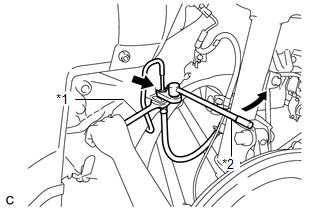
(b) Using a union nut wrench, disconnect the brake line while holding the rear flexible hose with a wrench. Text in Illustration
NOTICE:
|
|
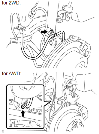
(c) Remove the clip.
|
(d) Remove the bolt and rear flexible hose from the absorber bracket. |
|
Installation
INSTALLATION
CAUTION / NOTICE / HINT
NOTICE:
- Because the left and right rear flexible hoses are not interchangeable, verify the part number when installing the flexible hoses.
- If the hoses are to be reused, connect them after checking the identification marks placed when each hose was disconnected.
PROCEDURE
1. INSTALL REAR FLEXIBLE HOSE
|
(a) Connect the rear flexible hose to the disc brake cylinder assembly with a new union bolt and a new gasket. Torque: 29 N·m {300 kgf·cm, 22 ft·lbf} HINT: Install the rear flexible hose lock securely into the lock hole in the rear disc brake cylinder assembly. |
|
.png)
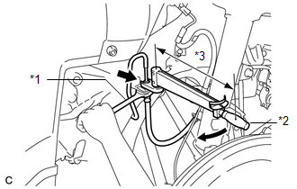
(b) Install the rear flexible hose to the bracket with a new clip.
NOTICE:
Install the clip as far as it will go.
|
(c) Using a union nut wrench, connect the brake line to the rear brake flexible hose while holding the flexible hose with a wrench. Text in Illustration
Torque: Specified Tightening Torque : 15 N·m {155 kgf·cm, 11 ft·lbf} NOTICE:
HINT:
|
|
|
(d) Install the rear flexible hose to the absorber bracket with the bolt. Torque: 19 N·m {192 kgf·cm, 14 ft·lbf} |
|
.png)
2. FILL RESERVOIR WITH BRAKE FLUID
.gif)
3. BLEED BRAKE LINE
4. INSPECT FOR BRAKE FLUID LEAK
5. INSPECT FLUID LEVEL IN RESERVOIR
6. INSTALL REAR WHEEL
Torque:
103 N·m {1050 kgf·cm, 76 ft·lbf}
 Installation
INSTALLATION
PROCEDURE
1. TEMPORARILY TIGHTEN REAR DISC BRAKE BLEEDER PLUG
(a) Temporarily tighten the rear disc brake bleeder plug.
HINT:
Fully tighten the rear disc brake bleeder plug after ble ...

Other materials about Toyota Venza:
Components
COMPONENTS
ILLUSTRATION
ILLUSTRATION
ILLUSTRATION
ILLUSTRATION
ILLUSTRATION
...
Installation
INSTALLATION
PROCEDURE
1. INSTALL CHECK VALVE GROMMET
(a) Install a new check valve grommet to the brake booster assembly.
2. INSTALL BRAKE VACUUM CHECK VALVE ASSEMBLY
(a) Install the brake vacuum check valve assembly to the brake booster assembly.
3. IN ...
Evaporative Emission System Switching Valve Control Circuit High (P2420)
DTC SUMMARY
DTC No.
Monitoring Item
Malfunction Detection Condition
Trouble Area
Detection Timing
Detection Logic
P2420
Vent valve stuck open (vent)
Follo ...

0.1625