Toyota Venza: Engine Oil Cooler
Components
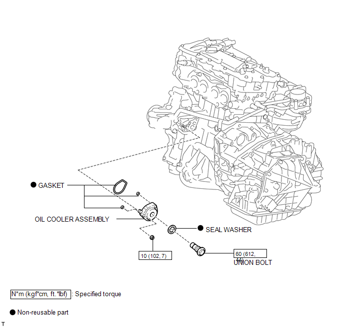
COMPONENTS
ILLUSTRATION
Removal
REMOVAL
PROCEDURE
1. REMOVE EXHAUST MANIFOLD ASSEMBLY
HINT:
See page .gif)
2. DRAIN ENGINE OIL
3. DRAIN ENGINE COOLANT
4. REMOVE OIL COOLER ASSEMBLY
|
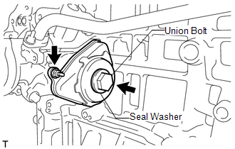
(a) Remove the nut, union bolt, seal washer and oil cooler assembly. |
|
(b) Remove the 3 gaskets from the oil cooler assembly.
Inspection
INSPECTION
PROCEDURE
1. INSPECT ENGINE OIL COOLER
(a) Visually check the engine oil cooler for cracks or damage.
If cracks or damage are found, replace the engine oil cooler.
Installation
INSTALLATION
PROCEDURE
1. INSTALL OIL COOLER ASSEMBLY
(a) Clean the oil cooler contact surface on the cooler mounting.
(b) Apply a light coat of engine oil to 3 new gaskets.
(c) Install the 3 new gaskets to the oil cooler assembly.
(d) Temporarily install the oil cooler assembly with the union bolt, nut and a new seal washer.
|
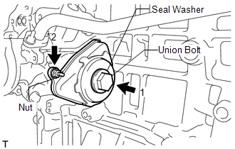
(e) Tighten the bolt and nut in several steps, in the sequence shown in the illustration. Torque: Union Bolt : 60 N·m {612 kgf·cm, 44 ft·lbf} Nut : 10 N·m {102 kgf·cm, 7 ft·lbf} |
|
2. INSTALL EXHAUST MANIFOLD ASSEMBLY
HINT:
See page .gif)
3. ADD ENGINE OIL
4. ADD ENGINE COOLANT
5. INSPECT FOR OIL LEAK
6. INSPECT ENGINE OIL LEVEL

 Lubrication System
On-vehicle Inspection
ON-VEHICLE INSPECTION
PROCEDURE
1. INSPECT ENGINE OIL LEVEL
(a) Warm up the engine, stop it and wait 5 minutes. The engine oil level should
be between the low level mark ...
Other materials about Toyota Venza:
Reassembly
REASSEMBLY
PROCEDURE
1. INSTALL SHIFT LOCK CONTROL COMPUTER SUB-ASSEMBLY
(a) Engage the 3 claws to install the shift lock control computer sub-assembly.
(b) Connect the connector.
2. INSTALL LOWER ...
Removal
REMOVAL
PROCEDURE
1. REMOVE FRONT SEAT HEADREST ASSEMBLY
2. REMOVE FRONT SEAT REAR OUTER TRACK COVER
3. REMOVE FRONT SEAT REAR INNER TRACK COVER
4. REMOVE FRONT SEAT ASSEMBLY
5. REMOVE RECLINING POWER SEAT SWITCH KNOB
6. REMOVE SLIDE AND VER ...
Torque Sensor Zero Point Adjustment Incomplete (C1516,C1526)
DESCRIPTION
These DTCs do not indicate a malfunction. The power steering ECU stores these
DTCs when it determines that the rotation angle sensor value initialization and
torque sensor zero point calibration are incomplete.
DTC No.
D ...

0.1398