
Toyota Venza: Headlight (HI-BEAM) Circuit
DESCRIPTION
- for Halogen Headlight:
The main body ECU (driver side junction block assembly) controls the high beam headlights.
WIRING DIAGRAM
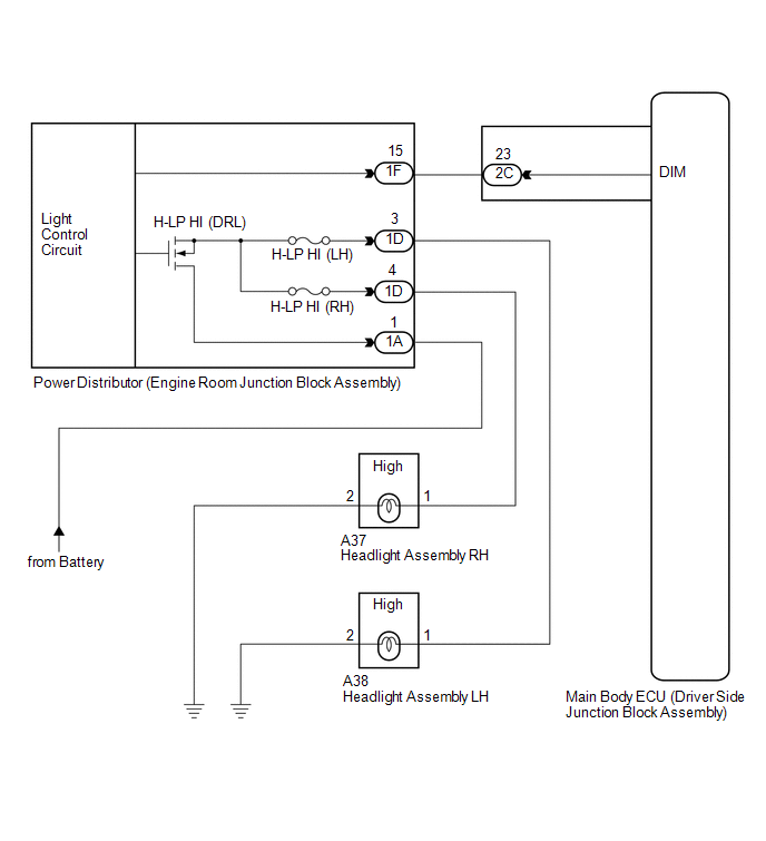
CAUTION / NOTICE / HINT
NOTICE:
Inspect the fuses for circuits related to this system before performing the following inspection procedure.
PROCEDURE
|
1. |
CHECK HEADLIGHT |
(a) Check the operation of low beam headlights.
OK:
Low beam headlights operate normally.
| NG | .gif) |
GO TO PROBLEM SYMPTOMS TABLE |
|
.gif)
|
2. |
PERFORM ACTIVE TEST USING TECHSTREAM |
(a) Connect the Techstream to the DLC3.
(b) Turn the ignition switch to ON.
(c) Turn the Techstream on.
(d) Enter the following menus: Body Electrical / Main Body / Active Test.
(e) Check that the relay operates.
Main Body|
Tester Display |
Test Part |
Control Range |
Diagnostic Note |
|---|---|---|---|
|
Head Light (HI) |
High beam headlight relay |
ON/OFF |
- |
OK:
Relay operates. (High beam headlights illuminate.)
| OK | |
PROCEED TO NEXT SUSPECTED AREA SHOWN IN PROBLEM SYMPTOMS TABLE |
|
|
3. |
CHECK HARNESS AND CONNECTOR (SHORT IN RELAY-DRIVEN CIRCUIT) |
HINT:
When a short circuit occurs between the power distributor (engine room junction block assembly) and high beam headlight bulb, a fail-safe function operates to stop the H-LP HI relay operation.
|
(a) Remove the H-LP HI (RH) fuse from the power distributor (engine room junction block assembly). |
|
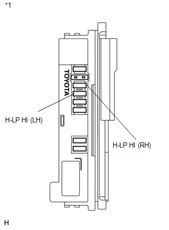
(b) Turn the light control switch to the head position and turn the dimmer switch to the high position.
(c) Check if the high beam headlight LH illuminates.
(d) Turn the dimmer switch to the low position.
(e) Install the H-LP HI (RH) fuse and remove the H-LP HI (LH) fuse.
(f) Turn the dimmer switch to the high position.
(g) Check if the high beam headlight RH illuminates.
OK:
Either high beam headlight LH or RH illuminates.
Text in Illustration|
*1 |
Power Distributor (Engine Room Junction Block Assembly) |
| NG | |
REPAIR OR REPLACE HARNESS OR CONNECTOR (FUSE - BODY GROUND) |
|
|
4. |
INSPECT POWER DISTRIBUTOR (ENGINE ROOM JUNCTION BLOCK ASSEMBLY) |
|
(a) Remove the power distributor (engine room junction block assembly) from the engine room relay block. |
|
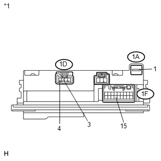
(b) Connect a positive (+) lead from the battery to terminal 1A-1.
(c) Connect a negative (-) lead from the battery to terminal 1F-15.
(d) Measure the voltage according to the value(s) in the table below.
Standard Voltage:
|
Tester Connection |
Condition |
Specified Condition |
|---|---|---|
|
1D-3 - Battery negative |
Always |
11 to 14 V |
|
1D-4 - Battery negative |
Always |
11 to 14 V |
|
*1 |
Component without harness connected (Power Distributor (Engine Room Junction Block Assembly)) |
| NG | |
REPLACE POWER DISTRIBUTOR (ENGINE ROOM JUNCTION BLOCK ASSEMBLY) |
|
|
5. |
CHECK HARNESS AND CONNECTOR (ENGINE ROOM JUNCTION BLOCK ASSEMBLY - MAIN BODY ECU) |
|
(a) Disconnect the 1F power distributor (engine room junction block assembly) connector. |
|
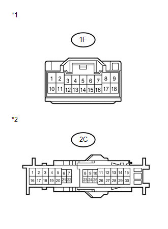
(b) Disconnect the 2C main body ECU (driver side junction block assembly) connector.
(c) Measure the resistance according to the value(s) in the table below.
Standard Resistance:
|
Tester Connection |
Condition |
Specified Condition |
|---|---|---|
|
1F-15 - 2C-23 |
Always |
Below 1 Ω |
|
2C-23 - Body ground |
Always |
10 kΩ or higher |
|
*1 |
Front view of wire harness connector (to Power Distributor (Engine Room Junction Block Assembly)) |
|
*2 |
Front view of wire harness connector (to Main Body ECU (Driver Side Junction Block Assembly)) |
| OK | |
REPLACE MAIN BODY ECU (DRIVER SIDE JUNCTION BLOCK ASSEMBLY) |
| NG | |
REPAIR OR REPLACE HARNESS OR CONNECTOR (FUSE - BODY GROUND) |
 Daytime Running Light Relay Circuit
DESCRIPTION
The main body ECU (driver side junction block assembly) controls the daytime
running lights.
WIRING DIAGRAM
1. for Halogen Headlight
2. for HID Headlight
PROCEDURE
1 ...
 Front Fog Light Circuit
DESCRIPTION
The main body ECU (driver side junction block assembly) controls the fog light
relay.
WIRING DIAGRAM
CAUTION / NOTICE / HINT
NOTICE:
Inspect the fuses for circuits related to this ...
Other materials about Toyota Venza:
Components
COMPONENTS
ILLUSTRATION
ILLUSTRATION
ILLUSTRATION
ILLUSTRATION
ILLUSTRATION
...
AWD Warning Light does not Come ON
DESCRIPTION
Refer to "AWD Warning Light Remains ON" (See page
).
WIRING DIAGRAM
Refer to "AWD Warning Light Remains ON" (See page
).
CAUTION / NOTICE / HINT
Check the condition of each related circuit connector before troubleshooti ...
Repair
REPAIR
PROCEDURE
1. REPAIR INTAKE VALVE SEAT
NOTICE:
Repair the seat while checking the seating position.
Keep the lip free of foreign matter.
Take off the cutter gradually to make the intake valve seat smooth.
(a) Usin ...

0.1446