Toyota Venza: Power Back Door Closer Switch
Components
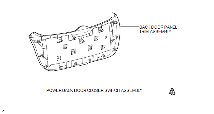
COMPONENTS
ILLUSTRATION
Removal
REMOVAL
PROCEDURE
1. REMOVE BACK DOOR PANEL TRIM ASSEMBLY
.gif)
2. REMOVE POWER BACK DOOR CLOSER SWITCH ASSEMBLY
|
(a) Disconnect the connector. |
|
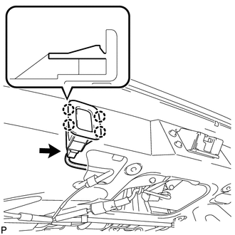
(b) Disengage the 4 claws and remove the power back door closer switch assembly.
Inspection
INSPECTION
PROCEDURE
1. INSPECT POWER BACK DOOR CLOSER SWITCH
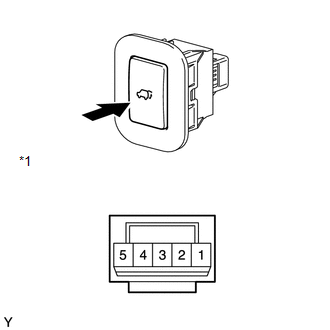
(a) Check that the switch function.
(1) Measure the resistance according to the value(s) in the table below.
Standard Resistance:
|
Tester Connection |
Condition |
Specified Condition |
|---|---|---|
|
4 - 1 |
Pushed (ON) |
Below 1 Ω |
|
4 - 1 |
Free (OFF) |
10 kΩ or higher |
|
*1 |
Component without harness connected (Power Back Door Closer Switch) |
If the result is not as specified, replace the switch.
|
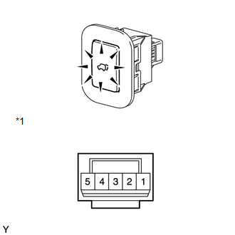
(b) Check that the switch illuminates. (1) Apply battery voltage to the power back door closer switch and check that the switch illuminates. OK:
If the result is not as specified, replace the switch. |
|
Installation
INSTALLATION
PROCEDURE
1. INSTALL POWER BACK DOOR CLOSER SWITCH ASSEMBLY
|
(a) Engage the 4 claws to install the power back door closer switch assembly. |
|
.png)
(b) Connect the connector.
2. INSTALL BACK DOOR PANEL TRIM ASSEMBLY
.gif)
 Removal
REMOVAL
PROCEDURE
1. REMOVE FRONT WHEEL LH
2. REMOVE FRONT FENDER OUTSIDE MOULDING LH
3. REMOVE FRONT FENDER LINER LH
(a) Using a screwdriver, turn the pin 90 degrees and remove the ...
 Power Back Door Control Switch
Components
COMPONENTS
ILLUSTRATION
Inspection
INSPECTION
PROCEDURE
1. INSPECT POWER BACK DOOR OPENER / CLOSER SWITCH
(a) Measure the resistance of the switch.
Standard resistance:
...
Other materials about Toyota Venza:
Precaution
PRECAUTION
1. EXPRESSIONS OF IGNITION SWITCH
(a) The type of ignition switch used on this model differs according to the specifications
of the vehicle. The expressions listed in the table below are used in this section.
Switch Type
I ...
ECU Power Source Circuit
DESCRIPTION
This circuit provides power for main body ECU (driver side junction block assembly)
operation.
WIRING DIAGRAM
PROCEDURE
1.
CHECK DRIVER SIDE JUNCTION BLOCK ASSEMBLY (MAIN BODY ECU (POWER SOURCE))
...
Adjustment
ADJUSTMENT
PROCEDURE
1. INSPECT AND ADJUST BRAKE PEDAL HEIGHT
(a) Check the brake pedal height.
(1) Turn back the carpet.
(2) Measure the brake pedal height from the dash panel to the bottom
edge of the brake pedal pad.
Text in Illustrat ...

0.1347