Toyota Venza: Power Back Door Control Switch
Components
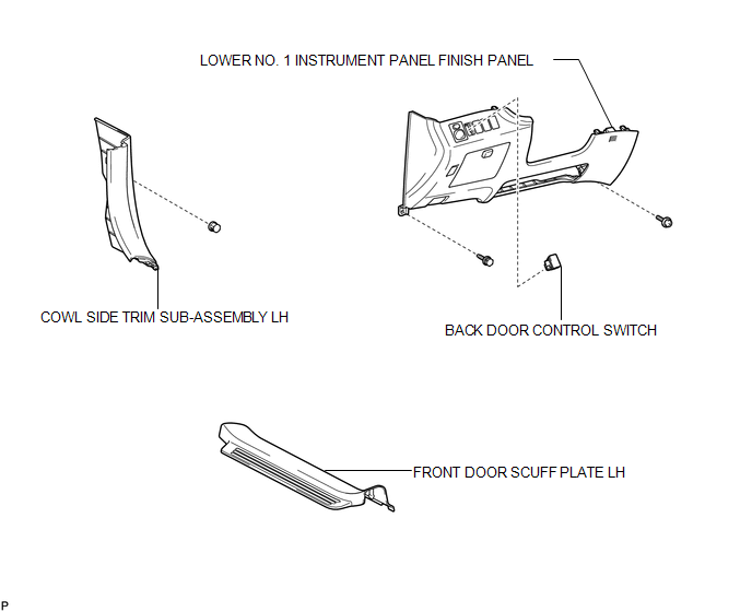
COMPONENTS
ILLUSTRATION
Inspection
INSPECTION
PROCEDURE
1. INSPECT POWER BACK DOOR OPENER / CLOSER SWITCH
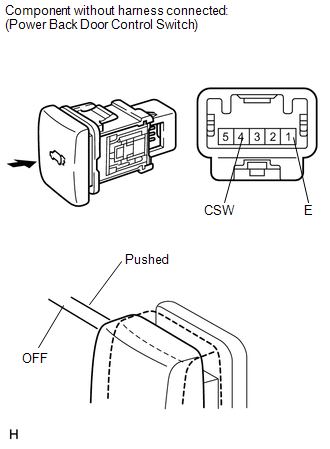
(a) Measure the resistance of the switch.
Standard resistance:
|
Tester Connection |
Condition |
Specified Condition |
|---|---|---|
|
1(E) - 4(CSW) |
Pushed (ON) |
Below 1 Ω |
|
1(E) - 4(CSW) |
Free (OFF) |
10 kΩ or higher |
If the result is not as specified, replace the switch.
(b) Check that the switch illuminates.
Standard resistance:
|
Measurement Condition |
Specified Condition |
|---|---|
|
Battery positive (+) → 3 (ILL+) Battery negative (-) → 2 (ILL-) |
Illuminates |
If the result is not as specified, replace the switch.
Removal
REMOVAL
PROCEDURE
1. REMOVE FRONT DOOR SCUFF PLATE LH
.gif)
2. REMOVE COWL SIDE TRIM SUB-ASSEMBLY LH
3. REMOVE LOWER NO. 1 INSTRUMENT PANEL FINISH PANEL
4. REMOVE BACK DOOR CONTROL SWITCH
|
(a) Disengage the 2 claws and remove the back door control switch. |
|
Installation
INSTALLATION
PROCEDURE
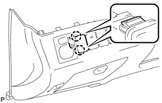
1. INSTALL BACK DOOR CONTROL SWITCH
|
(a) Engage the 2 claws to install the back door control switch. |
|
.png)
2. INSTALL LOWER NO. 1 INSTRUMENT PANEL FINISH PANEL
.gif)
3. INSTALL COWL SIDE TRIM SUB-ASSEMBLY LH
4. INSTALL FRONT DOOR SCUFF PLATE LH
 Power Back Door Closer Switch
Components
COMPONENTS
ILLUSTRATION
Removal
REMOVAL
PROCEDURE
1. REMOVE BACK DOOR PANEL TRIM ASSEMBLY
2. REMOVE POWER BACK DOOR CLOSER SWITCH ASSEMBLY
(a) Disconnect the con ...

Other materials about Toyota Venza:
Abbreviations Used In Manual
ABBREVIATIONS USED IN MANUAL
Abbreviation
Meaning
ABS
Anti-Lock Brake System
A/C
Air Conditioner
AC
Alternating Current
ACC
A ...
Uniform Tire Quality Grading
This information has been prepared in accordance with regulations issued by the
National Highway Traffic Safety Administration of the U.S. Department of Transportation.
It provides the purchasers and/or prospective purchasers of Toyota vehicles with
infor ...
Removal
REMOVAL
PROCEDURE
1. DRAIN AUTOMATIC TRANSAXLE FLUID
2. REMOVE FRONT FRAME ASSEMBLY
See page
3. SUPPORT ENGINE ASSEMBLY
4. REMOVE BELT
5. REMOVE AUTOMATIC TRANSAXLE OIL PAN SUB-ASSEMBLY
(a) Remove the 18 bolts and automatic transa ...

0.134