Toyota Venza: Power Back Door cannot be Operated Using Any Switch
DESCRIPTION
When the power back door cannot be operated using any switch, one of the following may be the cause: 1) initialization of the power back door ECU (power back door motor unit), 2) power back door touch sensor circuit, 3) power back door main switch circuit, 4) back door closer system, 5) meter/gauge system, 6) main body ECU (driver side junction block assembly) or 7) power back door ECU (power back door motor unit).
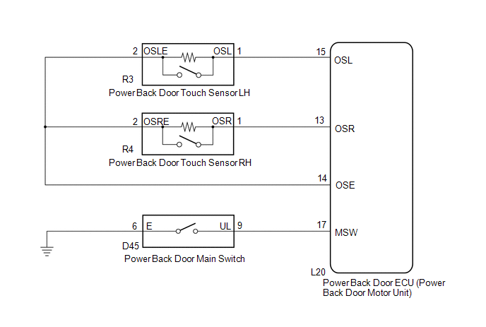
WIRING DIAGRAM
PROCEDURE
|
1. |
INITIALIZE POWER BACK DOOR ECU |
(a) Perform the initialization for the power back door ECU (power back door motor
unit) (See page .gif) ).
).
|
.gif)
|
2. |
CHECK POWER BACK DOOR SYSTEM |
(a) Check the power back door system operation (See page
).
OK:
Power back door system operates normally.
| OK | .gif) |
END |
|
|
3. |
CHECK BACK DOOR CLOSER SYSTEM |
(a) Check back door closer system operation (See page
).
OK:
Back door closer system operates normally.
| NG | |
GO TO BACK DOOR CLOSER SYSTEM |
|
|
4. |
CHECK COMBINATION METER ASSEMBLY |
(a) Check shift position indicator operation and that the speedometer indicates 0 mph when the vehicle is stopped and the engine idling .
OK:
Combination meter operates normally.
| NG | |
GO TO METER/GAUGE SYSTEM |
|
|
5. |
CHECK DTC OUTPUT |
(a) Check for DTCs (See page ).
|
Result |
Proceed to |
|---|---|
|
DTC is not output |
A |
|
B2222 is output |
B |
|
B2225 is output |
C |
|
B2250 is output |
D |
|
B2251 is output |
E |
| B | |
GO TO OTHER FLOW CHART (B2222) |
| C | |
GO TO OTHER FLOW CHART (B2225) |
| D | |
GO TO OTHER FLOW CHART (B2250) |
| E | |
GO TO OTHER FLOW CHART (B2251) |
|
|
6. |
READ VALUE USING TECHSTREAM (BACK DOOR LOCK ASSEMBLY) |
(a) Connect the Techstream to the DLC3.
(b) Turn the ignition switch to ON.
(c) Turn the Techstream on.
(d) Enter the following menus: Body Electrical / Main Body / Data List.
(e) Check the Data List to determine if the back door lock assembly functions properly.
Main Body (Main Body ECU (Driver Side Junction Block Assembly))|
Tester Display |
Measurement Item/Range |
Normal Condition |
Diagnostic Note |
|---|---|---|---|
|
Back Door Open |
Back door lock / Permit or Prohibit |
Permit: Back door unlocked Prohibit: Back door locked |
- |
OK:
The back door functions as specified in the normal condition column.
| NG | |
REPLACE MAIN BODY ECU (DRIVER SIDE JUNCTION BLOCK ASSEMBLY) |
|
|
7. |
READ VALUE USING TECHSTREAM (BACK DOOR LOCK ASSEMBLY) |
(a) Connect the Techstream to the DLC3.
(b) Turn the ignition switch to ON.
(c) Turn the Techstream on.
(d) Enter the following menus: Body Electrical / Back Door / Data List.
(e) Check the Data List to determine if the back door lock assembly functions properly.
Back Door (Power Back Door ECU)|
Tester Display |
Measurement Item/Range |
Normal Condition |
Diagnostic Note |
|---|---|---|---|
|
Door Lock Status |
Back door lock condition signal / LOCK or UNLOCK |
LOCK: Back door locked UNLOCK: Back door unlocked |
- |
OK:
The back door functions as specified in the normal condition column.
| NG | |
REPLACE POWER BACK DOOR ECU (POWER BACK DOOR MOTOR UNIT) |
|
|
8. |
READ VALUE USING TECHSTREAM (POWER BACK DOOR TOUCH SENSOR) |
(a) Connect the Techstream to the DLC3.
(b) Turn the ignition switch to ON.
(c) Turn the Techstream on.
(d) Enter the following menus: Body Electrical / Back Door / Data List.
(e) Check the Data List to determine if the power back door touch sensor functions properly.
Back Door (Power Back Door ECU)|
Tester Display |
Measurement Item/Range |
Normal Condition |
Diagnostic Note |
|---|---|---|---|
|
PBD Touch Sensor (Left) |
Power back door touch sensor LH signal / ON , OFF or Open |
ON: Power back door touch sensor LH pressed OFF: Power back door touch sensor LH not pressed Open: Power back door touch sensor LH circuit open |
- |
|
PBD Touch Sensor (Right) |
Power back door touch sensor RH signal / ON , OFF or Open |
ON: Power back door touch sensor RH pressed OFF: Power back door touch sensor RH not pressed Open: Power back door touch sensor RH circuit open |
- |
|
Result |
Proceed to |
|---|---|
|
On the Techstream screen, ON or OFF will be displayed accordingly. |
A |
|
On the Techstream screen, ON or OFF will not be displayed accordingly or Open is displayed. |
B |
| B | |
GO TO OTHER FLOW CHART (TOUCH SENSOR CIRCUIT) |
|
|
9. |
READ VALUE USING TECHSTREAM (POWER BACK DOOR MAIN SWITCH) |
(a) Connect the Techstream to the DLC3.
(b) Turn the ignition switch to ON.
(c) Turn the Techstream on.
(d) Enter the following menus: Body Electrical / Back Door / Data List.
(e) Check the Data List to determine if the power back door main switch functions properly.
Back Door (Power Back Door ECU)|
Tester Display |
Measurement Item/Range |
Normal Condition |
Diagnostic Note |
|---|---|---|---|
|
PBD Main SW |
Power back door main switch / ON or OFF |
ON: Power back door main switch on OFF: Power back door main switch off |
- |
OK:
The power back door main switch functions as specified in the normal condition column.
| OK | |
REPLACE POWER BACK DOOR ECU (POWER BACK DOOR MOTOR UNIT) |
|
|
10. |
INSPECT POWER BACK DOOR MAIN SWITCH |
(a) Remove the power back door main switch (See page
).
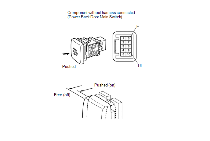
(b) Measure the resistance according to the value(s) in the table below.
Standard Resistance:
|
Tester Connection |
Switch Condition |
Specified Condition |
|---|---|---|
|
6 (E) - 9 (UL) |
Free (off) |
Below 1 Ω |
|
6 (E) - 9 (UL) |
Pushed (on) |
10 kΩ or higher |
| NG | |
REPLACE POWER BACK DOOR MAIN SWITCH |
|
|
11. |
CHECK HARNESS AND CONNECTOR (POWER BACK DOOR MAIN SWITCH - POWER BACK DOOR ECU) |
|
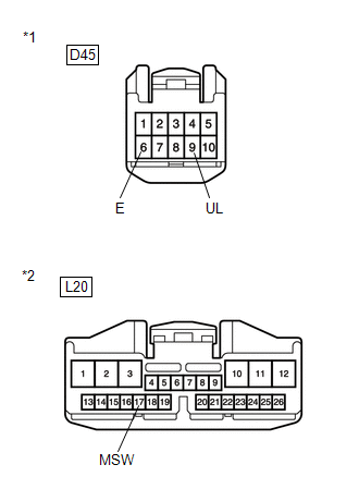
(a) Disconnect the D45 power back door main switch connector and L20 power back door ECU connector. |
|
(b) Measure the resistance according to the value(s) in the table below.
Standard Resistance:
|
Tester Connection |
Condition |
Specified Condition |
|---|---|---|
|
D45-9 (UL) - L20-17 (MSW) |
Always |
Below 1 Ω |
|
D45-6 (E) - Body ground |
Always |
Below 1 Ω |
|
D45-9 (UL) - Body ground |
Always |
10 kΩ or higher |
|
*1 |
Front view of wire harness connector (to Power Back Door Main Switch) |
|
*2 |
Front view of wire harness connector (to Power Back Door ECU) |
| OK | |
REPLACE POWER BACK DOOR ECU (POWER BACK DOOR MOTOR UNIT) |
| NG | |
REPAIR OR REPLACE HARNESS OR CONNECTOR |
 Power Back Door cannot be Opened or Closed Using the Power Back Door Switch
DESCRIPTION
When the power back door cannot be opened or closed using the power back door
control switch, one of the following may be malfunctioning: 1) power back door control
switch circuit, 2) ...
 Power Back Door cannot be Closed Using the Power Back Door Closer Switch
DESCRIPTION
When the power back door cannot be closed using the power back door closer switch,
either of the following may be malfunctioning: 1) power back door closer switch
circuit or 2) power ...
Other materials about Toyota Venza:
Problem Symptoms Table
PROBLEM SYMPTOMS TABLE
Use the table below to help determine the cause of problem symptoms.
If multiple suspected areas are listed, the potential causes of the symptoms
are listed in order of probability in the "Suspected Area" column ...
Removal
REMOVAL
CAUTION / NOTICE / HINT
HINT:
When installing new name plates and emblem, heat the vehicle body, name plates
and emblem using a heat light.
Heating Temperature
Item
Temperature
Vehicle Body
40 to ...
Registration
REGISTRATION
CAUTION / NOTICE / HINT
NOTICE:
When the automatic transaxle is replaced, the transaxle compensation
code must be input into the TCM (proceed to Procedure 1). After the automatic
transaxle is reinstalled, the Quick Response (QR) ...

0.1211