Toyota Venza: Passenger Side Buckle Switch Circuit Malfunction (B1771)
DESCRIPTION
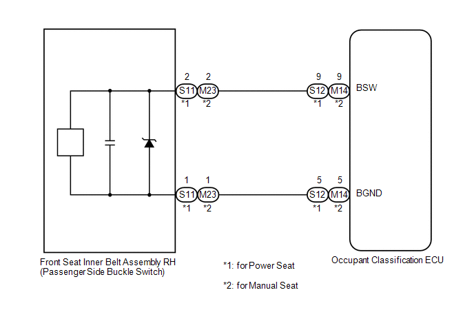
The passenger side buckle switch circuit consists of the occupant classification ECU and front seat inner belt assembly RH.
DTC B1771 is recorded when a malfunction is detected in the passenger side buckle switch circuit.
Troubleshoot DTC B1771 first if DTCs B1771 and B1795 are output simultaneously.
|
DTC No. |
DTC Detection Condition |
Trouble Area |
|---|---|---|
|
B1771 |
|
|
HINT:
When DTC B1650/32 is detected as a result of troubleshooting for the airbag system, check the DTCs stored in the occupant classification ECU. When DTC B1771 is output, perform troubleshooting for the DTC.
WIRING DIAGRAM
CAUTION / NOTICE / HINT
HINT:
- If troubleshooting (wire harness inspection) is difficult to perform, remove the front passenger seat installation bolts to see under the seat cushion.
- In the above case, hold the seat so that it does not fall down. Hold the seat only as necessary because holding the seat for a long period of time may cause seat rail deformation.
PROCEDURE
|
1. |
CHECK CONNECTORS |
(a) Turn the ignition switch off.
(b) Disconnect the cable from the negative (-) battery terminal.
(c) Check that the connectors are properly connected to the occupant classification ECU and front seat inner belt assembly RH.
OK:
The connectors are properly connected.
HINT:
If the connectors are not connected securely, reconnect the connectors and proceed to the next inspection.
(d) Disconnect the connectors from the occupant classification ECU and front seat inner belt assembly RH.
(e) Check that the terminals of connectors are not damaged.
OK:
The terminals are not deformed or damaged.
Result|
Result |
Proceed to |
|---|---|
|
OK |
A |
|
NG (for Power seat) |
B |
|
NG (for Manual seat) |
C |
| B | .gif) |
REPLACE FRONT SEAT WIRE RH |
| C | |
REPLACE NO. 2 FLOOR WIRE |
|
.gif)
|
2. |
CHECK FRONT SEAT WIRE RH (SHORT TO B+) |
|
(a) Connect the cable to the negative (-) battery terminal. |
|
(b) Turn the ignition switch to ON.
(c) Measure the voltage according to the value(s) in the table below.
Standard Voltage:
for Power Seat
|
Tester Connection |
Switch Condition |
Specified Condition |
|---|---|---|
|
S12-9 (BSW) - Body ground |
Ignition switch ON |
Below 1 V |
|
S12-5 (BGND) - Body ground |
Ignition switch ON |
Below 1 V |
for Manual Seat
|
Tester Connection |
Switch Condition |
Specified Condition |
|---|---|---|
|
M14-9 (BSW) - Body ground |
Ignition switch ON |
Below 1 V |
|
M14-5 (BGND) - Body ground |
Ignition switch ON |
Below 1 V |
|
Result |
Proceed to |
|---|---|
|
OK |
A |
|
NG (for Power seat) |
B |
|
NG (for Manual seat) |
C |
|
*1 |
Front Seat Inner Belt Assembly RH |
|
*2 |
Occupant Classification ECU |
|
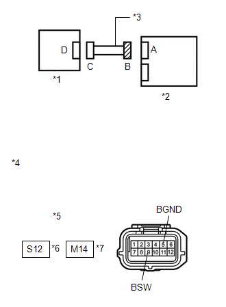
*3 |
Front Seat Wire RH |
|
*4 |
Front view of wire harness connector (to Occupant Classification ECU) |
|
*5 |
Connector B |
|
*6 |
for Power Seat |
|
*7 |
for Manual Seat |
| B | |
REPLACE FRONT SEAT WIRE RH |
| C | |
REPLACE NO. 2 FLOOR WIRE |
|
|
3. |
CHECK FRONT SEAT WIRE RH (OPEN) |
(a) Turn the ignition switch off.
(b) Disconnect the cable from the negative (-) battery terminal.
(c) Using SST, connect terminals 2 and 1 of connector C.
NOTICE:
Do not forcibly insert SST into the terminals of the connector when connecting.
SST: 09843-18040
(d) Measure the resistance according to the value(s) in the table below.
Standard Resistance:
for Power Seat
|
Tester Connection |
Condition |
Specified Condition |
|---|---|---|
|
S12-9 (BSW) - S12-5 (BGND) |
Always |
Below 1 Ω |
for Manual Seat
|
Tester Connection |
Condition |
Specified Condition |
|---|---|---|
|
M14-9 (BSW) - M14-5 (BGND) |
Always |
Below 1 Ω |
|
Result |
Proceed to |
|---|---|
|
OK |
A |
|
NG (for Power seat) |
B |
|
NG (for Manual seat) |
C |
|
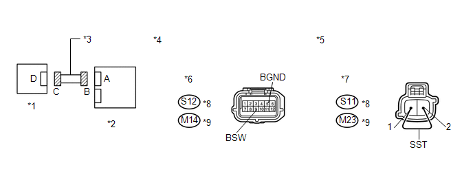
*1 |
Front Seat Inner Belt Assembly RH |
*2 |
Occupant Classification ECU |
|
*3 |
Front Seat Wire RH |
*4 |
Front view of wire harness connector (to Occupant Classification ECU) |
|
*5 |
Front view of wire harness connector (to Front Seat Inner Belt Assembly RH) |
*6 |
Connector B |
|
*7 |
Connector C |
*8 |
for Power Seat |
|
*9 |
for Manual Seat |
- |
- |
| B | |
REPLACE FRONT SEAT WIRE RH |
| C | |
REPLACE NO. 2 FLOOR WIRE |
|
|
4. |
CHECK FRONT SEAT WIRE RH (SHORT) |
|
(a) Disconnect SST from connector C. |
|
(b) Measure the resistance according to the value(s) in the table below.
Standard Resistance:
for Power Seat
|
Tester Connection |
Condition |
Specified Condition |
|---|---|---|
|
S12-9 (BSW) - S12-5 (BGND) |
Always |
1 MΩ or higher |
for Manual Seat
|
Tester Connection |
Condition |
Specified Condition |
|---|---|---|
|
M14-9 (BSW) - M14-5 (BGND) |
Always |
1 MΩ or higher |
|
Result |
Proceed to |
|---|---|
|
OK |
A |
|
NG (for Power seat) |
B |
|
NG (for Manual seat) |
C |
|
*1 |
Front Seat Inner Belt Assembly RH |
|
*2 |
Occupant Classification ECU |
|
*3 |
Front Seat Wire RH |
|
*4 |
Front view of wire harness connector (to Occupant Classification ECU) |
|
*5 |
Connector B |
|
*6 |
for Power Seat |
|
*7 |
for Manual Seat |
| B | |
REPLACE FRONT SEAT WIRE RH |
| C | |
REPLACE NO. 2 FLOOR WIRE |
|
|
5. |
CHECK FRONT SEAT WIRE RH (SHORT TO GROUND) |
|
(a) Measure the resistance according to the value(s) in the table below. Standard Resistance: for Power Seat
for Manual Seat
|
|
|
Result |
Proceed to |
|---|---|
|
OK |
A |
|
NG (for Power seat) |
B |
|
NG (for Manual seat) |
C |
|
*1 |
Front Seat Inner Belt Assembly RH |
|
*2 |
Occupant Classification ECU |
|
*3 |
Front Seat Wire RH |
|
*4 |
Front view of wire harness connector (to Occupant Classification ECU) |
|
*5 |
Connector B |
|
*6 |
for Power Seat |
|
*7 |
for Manual Seat |
| B | |
REPLACE FRONT SEAT WIRE RH |
| C | |
REPLACE NO. 2 FLOOR WIRE |
|
|
6. |
CHECK DTC |
(a) Connect the connectors to the occupant classification ECU and front seat inner belt assembly RH.
(b) Connect the cable to the negative (-) battery terminal.
(c) Turn the ignition switch to ON.
(d) Clear the DTCs stored in the occupant classification ECU (See page
.gif) ).
).
(e) Clear the DTCs stored in the center airbag sensor assembly (See page
).
(f) Turn the ignition switch off.
(g) Turn the ignition switch to ON.
(h) Check for DTCs (See page ).
OK:
DTC B1771 is not output.
HINT:
Codes other than DTC B1771 may be output at this time, but they are not related to this check.
| OK | |
USE SIMULATION METHOD TO CHECK |
|
|
7. |
REPLACE FRONT SEAT INNER BELT ASSEMBLY RH |
(a) Turn the ignition switch off.
(b) Disconnect the cable from the negative (-) battery terminal.
(c) Replace the front seat inner belt assembly RH (See page
).
HINT:
Perform the inspection using parts from a normal vehicle if possible.
(d) Connect the cable to the negative (-) battery terminal.
(e) Turn the ignition switch to ON.
(f) Clear the DTCs stored in the occupant classification ECU (See page
).
(g) Clear the DTCs stored in the center airbag sensor assembly (See page
).
(h) Turn the ignition switch off.
(i) Turn the ignition switch to ON.
(j) Check for DTCs (See page ).
OK:
DTC B1771 is not output.
HINT:
Codes other than DTC B1771 may be output at this time, but they are not related to this check.
| OK | |
END |
|
|
8. |
REPLACE OCCUPANT CLASSIFICATION ECU |
(a) Turn the ignition switch off.
(b) Disconnect the cable from the negative (-) battery terminal.
(c) Replace the occupant classification ECU (See page
).
|
|
9. |
PERFORM ZERO POINT CALIBRATION |
(a) Connect the cable to the negative (-) battery terminal.
(b) Connect the Techstream to the DLC3.
(c) Turn the ignition switch to ON.
(d) Using the Techstream, perform Zero Point Calibration (See page
).
OK:
"Zero Point Calibration is complete." is displayed.
|
|
10. |
PERFORM SENSITIVITY CHECK |
(a) Using the Techstream, perform Sensitivity Check (See page
).
Standard:
27 to 33 kg (59.5 to 72.8 lb)
| NEXT | |
END |
 Front Occupant Classification Sensor RH Circuit Malfunction (B1781)
DESCRIPTION
The front occupant classification sensor RH circuit consists of the occupant
classification ECU and front occupant classification sensor RH.
DTC B1781 is recorded when a malfunction is ...
 Front Occupant Classification Sensor LH Circuit Malfunction (B1780)
DESCRIPTION
The front occupant classification sensor LH circuit consists of the occupant
classification ECU and front occupant classification sensor LH.
DTC B1780 is recorded when a malfunction is ...
Other materials about Toyota Venza:
Power Management Control ECU Communication Stop Mode
DESCRIPTION
Detection Item
Symptom
Trouble Area
Power Management Control ECU Communication Stop Mode
"Electric Power Control" is not displayed on the CAN Bus Check
screen ...
Fog light switch
The fog lights improve visibility in difficult driving conditions, such as
in rain or fog. The fog lights can be used when the headlights are on low beam.
Type A
1. Off
2. On
Type B
1. Off
2. On
Wiper intervals can be adjusted for intermittent ...
Does not Play even after Bluetooth Audio Mode is Selected
CAUTION / NOTICE / HINT
HINT:
Even if the portable player can play audio content, it may not be able to play
via the in-vehicle device. This does not necessarily indicate a malfunction of the
in-vehicle device.
PROCEDURE
1.
CHECK ...

0.1627