Toyota Venza: Parts Location
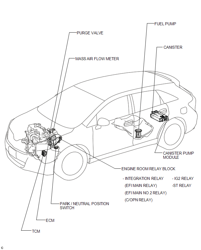
PARTS LOCATION
ILLUSTRATION
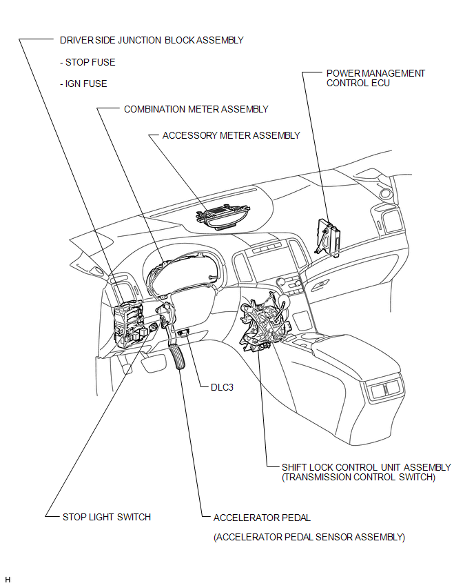
ILLUSTRATION
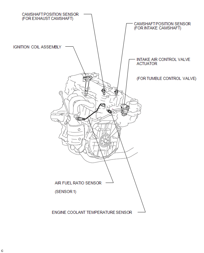
ILLUSTRATION
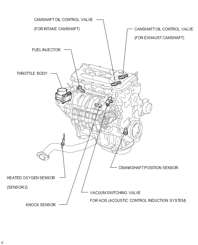
ILLUSTRATION
 Definition Of Terms
DEFINITION OF TERMS
Term
Definition
Monitor Description
Description of what the ECM monitors and how it detects malfunctions
(monitoring purpose ...
 How To Proceed With Troubleshooting
CAUTION / NOTICE / HINT
HINT:
*: Use the Techstream.
PROCEDURE
1.
VEHICLE BROUGHT TO WORKSHOP
NEXT
...
Other materials about Toyota Venza:
Inspection
INSPECTION
PROCEDURE
1. INSPECT THROTTLE BODY ASSEMBLY
Text in Illustration
*1
Component without harness connected
(Throttle Body)
(a) Check that the throttle valve opens and closes smoothly.
(b) Check that there is no ...
Cleaning and protecting the vehicle exterior
Perform the following to protect the vehicle and maintain it in prime condition.
• Working from top to bottom, liberally apply water to the vehicle body, wheel
wells and underside of the vehicle to remove any dirt and dust.
Wash the vehicle body using a ...
Reassembly
REASSEMBLY
PROCEDURE
1. BEARING POSITION
(a) Check each bearing position and installation direction.
Mark
Front Race Diameter
Inside / Outside mm (in.)
Thrust Bearing Diameter
Inside / Outside mm (in.)
...

0.1721