Toyota Venza: Parts Location
PARTS LOCATION
ILLUSTRATION
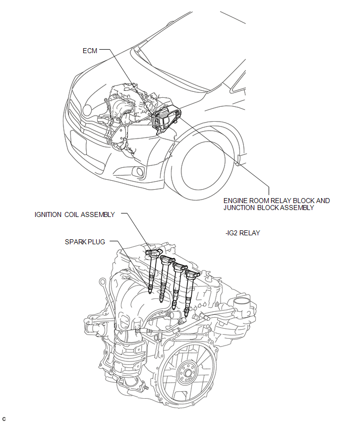
 Ignition System
...
 System Diagram
SYSTEM DIAGRAM
...
Other materials about Toyota Venza:
Components
COMPONENTS
ILLUSTRATION
ILLUSTRATION
ILLUSTRATION
ILLUSTRATION
ILLUSTRATION
ILLUSTRATION
...
Removal
REMOVAL
PROCEDURE
1. REMOVE COOL AIR INTAKE DUCT SEAL
(a) Using a clip remover, remove the 12 clips and cool air intake duct
seal.
2. REMOVE RADIATOR GRILLE
3. REMOVE FRONT BUMPER ASSEMBLY
...
Inspection
INSPECTION
PROCEDURE
1. INSPECT INTAKE AIR CONTROL VALVE (for ACIS)
(a) Inspect the diaphragm.
(1) Using a vacuum pump, apply a vacuum of 60 kPa (450 mmHg, 17.7 in.Hg)
or higher to the diaphragm chamber. Wait for 1 minute and check that the ...
© 2016-2026 Copyright www.tovenza.com

0.1595
0.1595