Toyota Venza: Parts Location
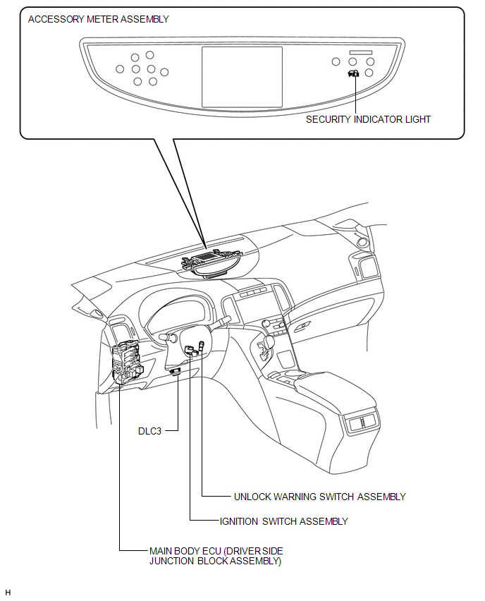
PARTS LOCATION
ILLUSTRATION
.png)
ILLUSTRATION
ILLUSTRATION
.png)
 Precaution
PRECAUTION
1. NOTICE FOR INITIALIZATION
NOTICE:
When disconnecting the cable from the negative (-) battery terminal, initialize
the following system after the cable is reconnected.
Sy ...
 System Description
SYSTEM DESCRIPTION
1. OUTLINE OF THEFT DETERRENT SYSTEM
The theft deterrent system can be set by locking the doors using the
transmitter or key, or by opening and closing the doors (for d ...
Other materials about Toyota Venza:
Removal
REMOVAL
PROCEDURE
1. REMOVE WINDSHIELD WIPER MOTOR AND LINK
(a) Remove the windshield wiper motor and link (See page
).
2. REMOVE OUTER COWL TOP PANEL SUB-ASSEMBLY
3. REMOVE COOL AIR INTAKE DUCT SEAL
4. REMOVE NO. 1 ENGINE COVER SUB-ASSEMBLY
...
How To Proceed With Troubleshooting
CAUTION / NOTICE / HINT
HINT:
Use the following procedure to troubleshoot the navigation system.
*: Use the Techstream.
PROCEDURE
1.
VEHICLE BROUGHT TO WORKSHOP
NEXT
...
Power Seat Position is not Memorized
DESCRIPTION
The main body ECU (driver side junction block assembly) receives seat memory
switch signals from the outer mirror control ECU assembly LH via CAN communication.
If the seat memory SET switch is being pressed when one of the M1 or M2 switches
...

0.1271