Toyota Venza: Parts Location
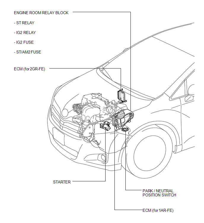
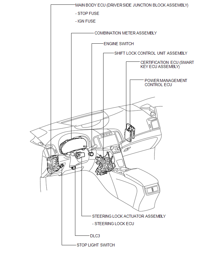
PARTS LOCATION
ILLUSTRATION
ILLUSTRATION
 Precaution
PRECAUTION
1. WHEN DISCONNECTING CABLE FROM NEGATIVE BATTERY TERMINAL
NOTICE:
When disconnecting the cable from the negative (-) battery terminal, initialize
the following systems after the cable ...
 System Diagram
SYSTEM DIAGRAM
Communication Table
Transmitting ECU
(Transmitter)
Receiving ECU
(Receiver)
Signal
Communication Method
Combinati ...
Other materials about Toyota Venza:
Components
COMPONENTS
ILLUSTRATION
ILLUSTRATION
ILLUSTRATION
ILLUSTRATION
ILLUSTRATION
...
Illumination Circuit
DESCRIPTION
Power is supplied to the radio and display receiver assembly and steering pad
switch assembly illumination when the light control switch is in the tail or head
position.
WIRING DIAGRAM
CAUTION / NOTICE / HINT
NOTICE:
The vehicle ...
Removal
REMOVAL
CAUTION / NOTICE / HINT
HINT:
Use the same procedure for the LH side and RH side.
The following procedure listed is for the LH side.
PROCEDURE
1. REMOVE FRONT WHEEL
2. DRAIN BRAKE FLUID
NOTICE:
If brake fluid leaks onto any pa ...
© 2016-2026 Copyright www.tovenza.com

0.1382
0.1382