
Toyota Venza: Parts Location
PARTS LOCATION
ILLUSTRATION
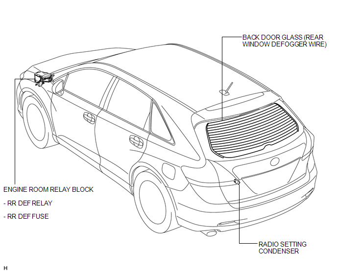
ILLUSTRATION
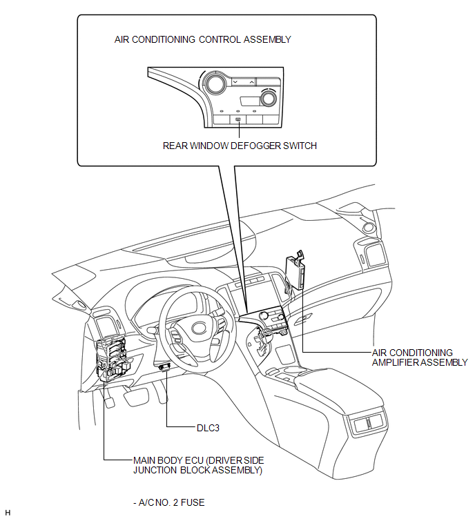

 Precaution
PRECAUTION
NOTICE:
When disconnecting the cable from the negative (-) battery terminal, initialize
the following systems after the cable is reconnected.
System Name
See Proc ...
Other materials about Toyota Venza:
Pressure Control Solenoid "G" Electrical (Shift Solenoid Valve SL4) (P2810)
DESCRIPTION
Changing from 1st to 6th is performed by the TCM turning shift solenoid valves
SL1, SL2, SL3, SL4 and SL on and off. If an open or short circuit occurs in any
of the shift solenoid valves, the TCM controls the remaining normal shift solenoid
...
On-vehicle Inspection
ON-VEHICLE INSPECTION
CAUTION / NOTICE / HINT
CAUTION:
Be sure to follow the correct removal and installation procedures of the rear
airbag sensor.
PROCEDURE
1. INSPECT REAR AIRBAG SENSOR (VEHICLE NOT INVOLVED IN COLLISION)
(a) Perform a diagnostic sys ...
Precaution
PRECAUTION
1. TROUBLESHOOTING PRECAUTION
NOTICE:
Be sure to read the supplemental restraint system precautions thoroughly
before servicing the brake system (See page
).
Care must be taken to replace each part properly as it could affect ...

0.1413